Cirkit Designer Logo
Cirkit Designer
Your all-in-one circuit design IDE
Home / 
Component Documentation

How to Use Adafruit 0.56 inch 7-segment LED Backpack Green: Examples, Pinouts, and Specs

Image of Adafruit 0.56 inch 7-segment LED Backpack Green
Cirkit Designer LogoDesign with Adafruit 0.56 inch 7-segment LED Backpack Green in Cirkit Designer

Introduction

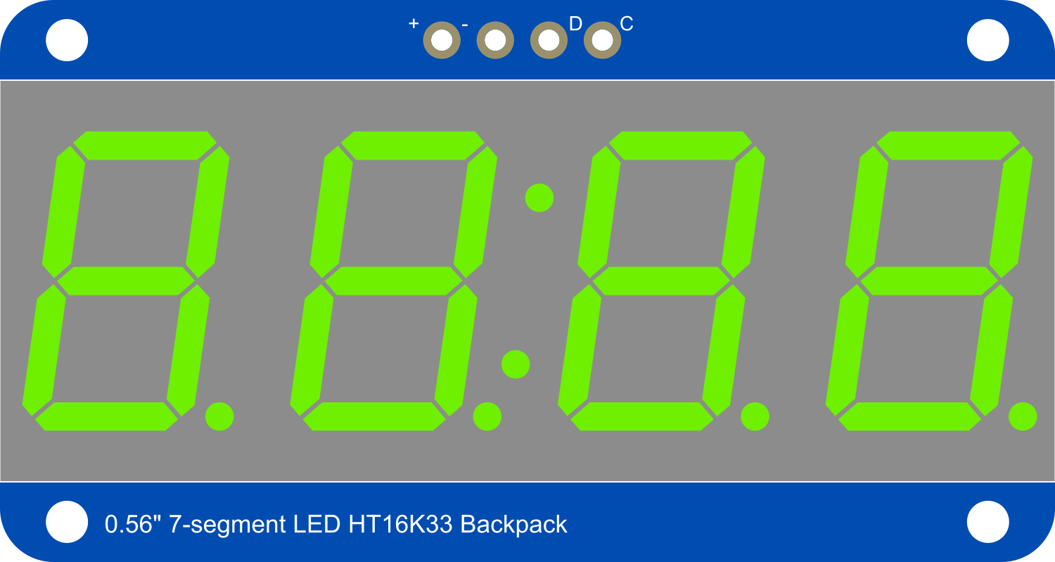
The Adafruit 0.56 inch 7-segment LED Backpack Green is a compact and easy-to-use module that simplifies the process of adding a bright, readable 7-segment display to your electronics projects. This component is ideal for displaying numerical information such as time, temperature, or any other data that can be represented in digits. The backpack uses I2C communication, reducing the number of pins required to control the display and making it perfect for use with microcontrollers like the Arduino UNO.

Explore Projects Built with Adafruit 0.56 inch 7-segment LED Backpack Green

Use Cirkit Designer to design, explore, and prototype these projects online. Some projects support real-time simulation. Click "Open Project" to start designing instantly!
Battery-Powered Sensor Hub with Adafruit QT Py RP2040 and OLED Display
Image of 512: A project utilizing Adafruit 0.56 inch 7-segment LED Backpack Green in a practical application
This circuit features an Adafruit QT Py RP2040 microcontroller interfacing with an MPU-6050 accelerometer, an Adafruit APDS-9960 sensor, and a 0.96" OLED display via I2C communication. It is powered by a 3.7V LiPo battery and includes a green LED with a current-limiting resistor connected to an analog pin of the microcontroller.
Cirkit Designer LogoOpen Project in Cirkit Designer
Wi-Fi Controlled ESP8266 with OLED Display and LED Indicators
Image of Final Project Circuit Rev 1: A project utilizing Adafruit 0.56 inch 7-segment LED Backpack Green in a practical application
This circuit features an ESP8266 NodeMCU microcontroller interfaced with a 0.96" OLED display for visual output and two LEDs (red and green) for status indication. The OLED is connected via I2C (SCK to D1, SDA to D2), while the LEDs are controlled by GPIO pins D3 and D4, with current-limiting resistors in series with the LED cathodes.
Cirkit Designer LogoOpen Project in Cirkit Designer
Battery-Powered Smart Light with Proximity Sensor and OLED Display using Adafruit QT Py RP2040
Image of lab: A project utilizing Adafruit 0.56 inch 7-segment LED Backpack Green in a practical application
This circuit is a portable, battery-powered system featuring an Adafruit QT Py RP2040 microcontroller that interfaces with an OLED display, a proximity sensor, an accelerometer, and an RGB LED strip. The system is powered by a lithium-ion battery with a step-up boost converter to provide 5V for the LED strip, and it includes a toggle switch for power control. The microcontroller communicates with the sensors and display via I2C.
Cirkit Designer LogoOpen Project in Cirkit Designer
Arduino UNO Controlled Dual Seven Segment Display with Pushbutton Interaction and AHT10 Temperature Sensor
Image of enel290: A project utilizing Adafruit 0.56 inch 7-segment LED Backpack Green in a practical application
This circuit features an Arduino UNO microcontroller connected to two seven-segment displays, a pushbutton, a red LED with a 330-ohm resistor, and an AHT10 temperature and humidity sensor. The Arduino controls the segments of the displays via its digital pins and reads the pushbutton state. The LED is used as an indicator, and the AHT10 sensor interfaces with the Arduino over I2C to provide environmental data.
Cirkit Designer LogoOpen Project in Cirkit Designer

Explore Projects Built with Adafruit 0.56 inch 7-segment LED Backpack Green

Use Cirkit Designer to design, explore, and prototype these projects online. Some projects support real-time simulation. Click "Open Project" to start designing instantly!
Image of 512: A project utilizing Adafruit 0.56 inch 7-segment LED Backpack Green in a practical application
Battery-Powered Sensor Hub with Adafruit QT Py RP2040 and OLED Display
This circuit features an Adafruit QT Py RP2040 microcontroller interfacing with an MPU-6050 accelerometer, an Adafruit APDS-9960 sensor, and a 0.96" OLED display via I2C communication. It is powered by a 3.7V LiPo battery and includes a green LED with a current-limiting resistor connected to an analog pin of the microcontroller.
Cirkit Designer LogoOpen Project in Cirkit Designer
Image of Final Project Circuit Rev 1: A project utilizing Adafruit 0.56 inch 7-segment LED Backpack Green in a practical application
Wi-Fi Controlled ESP8266 with OLED Display and LED Indicators
This circuit features an ESP8266 NodeMCU microcontroller interfaced with a 0.96" OLED display for visual output and two LEDs (red and green) for status indication. The OLED is connected via I2C (SCK to D1, SDA to D2), while the LEDs are controlled by GPIO pins D3 and D4, with current-limiting resistors in series with the LED cathodes.
Cirkit Designer LogoOpen Project in Cirkit Designer
Image of lab: A project utilizing Adafruit 0.56 inch 7-segment LED Backpack Green in a practical application
Battery-Powered Smart Light with Proximity Sensor and OLED Display using Adafruit QT Py RP2040
This circuit is a portable, battery-powered system featuring an Adafruit QT Py RP2040 microcontroller that interfaces with an OLED display, a proximity sensor, an accelerometer, and an RGB LED strip. The system is powered by a lithium-ion battery with a step-up boost converter to provide 5V for the LED strip, and it includes a toggle switch for power control. The microcontroller communicates with the sensors and display via I2C.
Cirkit Designer LogoOpen Project in Cirkit Designer
Image of enel290: A project utilizing Adafruit 0.56 inch 7-segment LED Backpack Green in a practical application
Arduino UNO Controlled Dual Seven Segment Display with Pushbutton Interaction and AHT10 Temperature Sensor
This circuit features an Arduino UNO microcontroller connected to two seven-segment displays, a pushbutton, a red LED with a 330-ohm resistor, and an AHT10 temperature and humidity sensor. The Arduino controls the segments of the displays via its digital pins and reads the pushbutton state. The LED is used as an indicator, and the AHT10 sensor interfaces with the Arduino over I2C to provide environmental data.
Cirkit Designer LogoOpen Project in Cirkit Designer

Technical Specifications

Key Features

  • Display Color: Green
  • Digit Height: 0.56 inches
  • Number of Digits: 4
  • Interface: I2C
  • I2C Addresses: 0x70 (default) - 0x77 (selectable with solder jumpers)
  • Input Voltage: 2.0V to 5.5V
  • Forward Current: 80mA (typical at 5V)

Pin Configuration

Pin Number Name Description
1 GND Ground connection
2 VCC Power supply (2.0V to 5.5V)
3 SDA I2C Data line
4 SCL I2C Clock line

Usage Instructions

Interfacing with Arduino

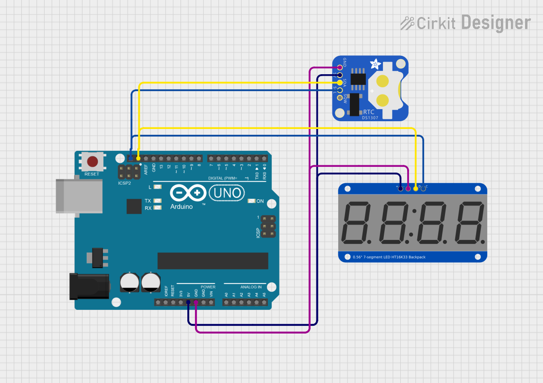
  1. Connecting the Display:

    • Connect the GND pin to the ground on your Arduino.
    • Connect the VCC pin to the 5V output on your Arduino.
    • Connect the SDA pin to the A4 (SDA) on your Arduino UNO.
    • Connect the SCL pin to the A5 (SCL) on your Arduino UNO.
  2. Library Installation:

    • Install the Adafruit LED Backpack library through the Arduino Library Manager or download it from the Adafruit GitHub repository.
  3. Initialization:

    • Include the Adafruit library in your sketch.
    • Create an object for the display, specifying the I2C address if it's different from the default.
  4. Displaying Numbers:

    • Use the print or write functions to display numbers on the LED.

Example Arduino Sketch

#include <Wire.h>
#include <Adafruit_GFX.h>
#include <Adafruit_LEDBackpack.h>

Adafruit_7segment matrix = Adafruit_7segment();

void setup() {
  matrix.begin(0x70); // Initialize the display with its I2C address
}

void loop() {
  matrix.print(1234, DEC); // Display the number 1234
  matrix.writeDisplay();    // Refresh the display to show the number
  delay(5000);              // Wait for 5 seconds
  matrix.clear();           // Clear the display
  matrix.writeDisplay();    // Refresh the display to show it's cleared
  delay(1000);              // Wait for 1 second
}

Important Considerations and Best Practices

  • Ensure that the power supply voltage does not exceed 5.5V to prevent damage to the LED display.
  • When using multiple displays, make sure to set unique I2C addresses for each one using the solder jumpers on the back.
  • Always call writeDisplay() after setting or clearing the display to update the actual LEDs.

Troubleshooting and FAQs

Common Issues

  • Display Not Lighting Up:

    • Check the wiring and ensure that the display is properly powered.
    • Verify that the I2C address used in the code matches the address set by the solder jumpers.
  • Garbled or Incorrect Output:

    • Ensure that the writeDisplay() function is called after setting the display value.
    • Check for loose connections or solder bridges on the I2C lines.

FAQs

Q: Can I use this display with a 3.3V system? A: Yes, the display can operate on a voltage range from 2.0V to 5.5V.

Q: How do I change the brightness of the display? A: The Adafruit LED Backpack library provides a setBrightness() function that can be used to adjust the brightness level.

Q: Can I display letters as well as numbers? A: The 7-segment display is primarily designed for numbers, but some letters can be approximated. The library provides support for a limited character set.

For further assistance or questions, refer to the Adafruit support forums or the product's FAQ section on the Adafruit website.