How to Use XY-MD02: Examples, Pinouts, and Specs
Introduction
The XY-MD02 is a wireless Bluetooth module designed for seamless communication between devices. It supports serial communication (UART) and operates using the Bluetooth 4.0 protocol, making it ideal for low-power and high-speed data transmission. This module is widely used in IoT applications, enabling microcontrollers to connect to smartphones, tablets, or other Bluetooth-enabled devices. Its compact size and ease of integration make it a popular choice for hobbyists and professionals alike.
Explore Projects Built with XY-MD02


Explore Projects Built with XY-MD02
Common Applications and Use Cases
- Wireless data transmission between microcontrollers and smartphones
- IoT devices and smart home automation
- Remote control systems
- Wireless sensor networks
- Robotics and industrial automation
Technical Specifications
The XY-MD02 module is designed to provide reliable and efficient Bluetooth communication. Below are its key technical specifications:
| Parameter | Value |
|---|---|
| Bluetooth Version | 4.0 (Low Energy) |
| Communication Protocol | UART (Serial Communication) |
| Operating Voltage | 3.3V to 6V |
| Operating Current | 8mA (typical) |
| Baud Rate | 9600 bps (default, configurable) |
| Transmission Range | Up to 10 meters (line of sight) |
| Dimensions | 37mm x 15mm x 7mm |
| Operating Temperature | -20°C to 70°C |
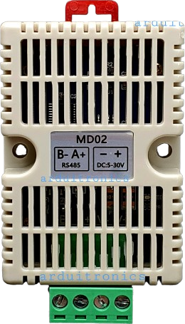
Pin Configuration and Descriptions
The XY-MD02 module has 6 pins, as described in the table below:
| Pin | Name | Description |
|---|---|---|
| 1 | VCC | Power supply input (3.3V to 6V). Connect to the power source. |
| 2 | GND | Ground. Connect to the ground of the circuit. |
| 3 | TXD | Transmit data pin. Sends serial data to the connected microcontroller. |
| 4 | RXD | Receive data pin. Receives serial data from the connected microcontroller. |
| 5 | EN (Key) | Enable pin. Used to switch between command and data modes. |
| 6 | STATE | Status indicator pin. High when connected to a device, low when disconnected. |
Usage Instructions
The XY-MD02 module is straightforward to use and can be easily integrated into a circuit. Below are the steps and best practices for using the module:
Connecting the XY-MD02 to a Microcontroller
- Power Supply: Connect the
VCCpin to a 3.3V or 5V power source and theGNDpin to the ground. - Serial Communication:
- Connect the
TXDpin of the module to theRXpin of the microcontroller. - Connect the
RXDpin of the module to theTXpin of the microcontroller.
- Connect the
- Enable Pin: Leave the
ENpin unconnected for normal operation. Pull it high to enter AT command mode. - Status Pin: Optionally, connect the
STATEpin to an LED or microcontroller input to monitor the connection status.
Example: Using XY-MD02 with Arduino UNO
Below is an example of how to use the XY-MD02 module with an Arduino UNO to send and receive data via Bluetooth.
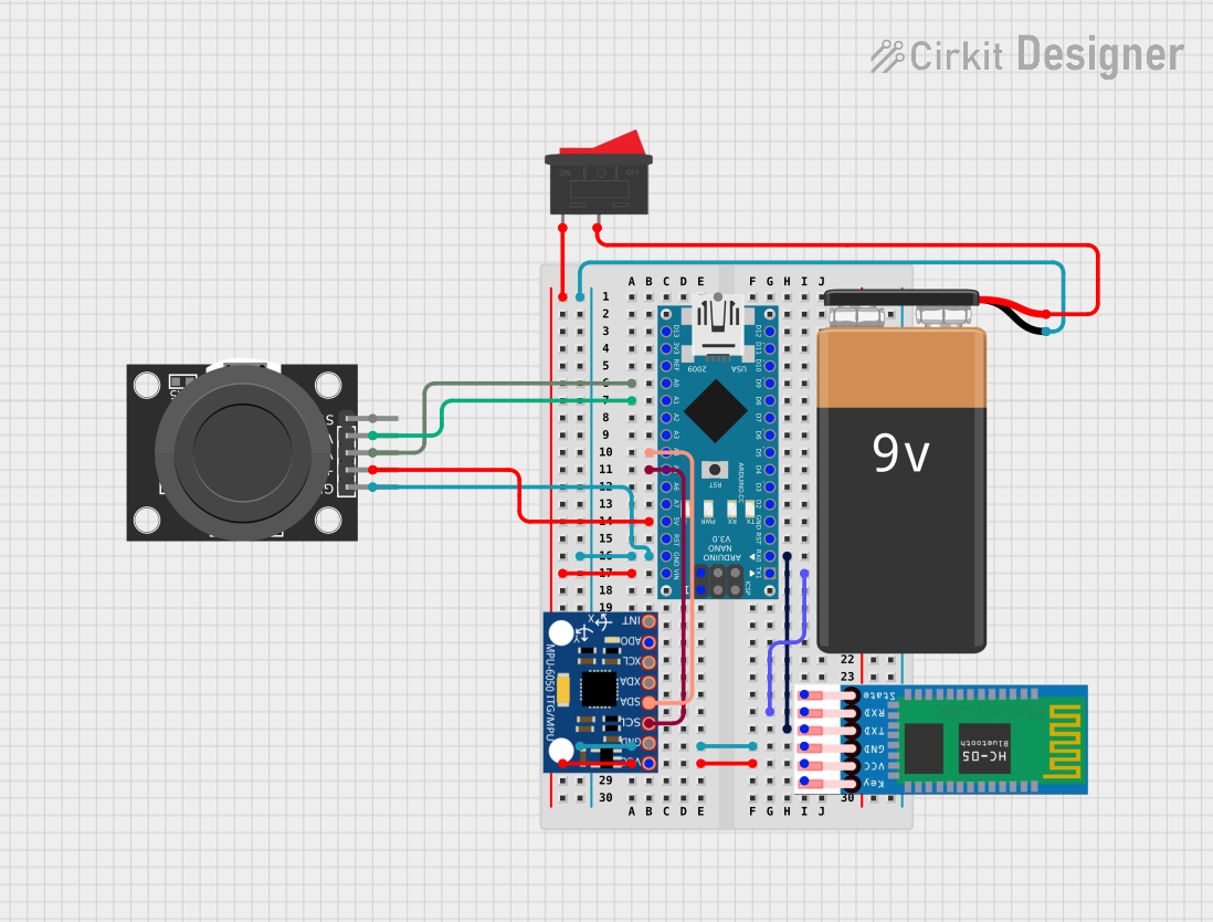
Circuit Diagram
- Connect
VCCto the 5V pin on the Arduino. - Connect
GNDto the GND pin on the Arduino. - Connect
TXDto pin 10 on the Arduino (software serial RX). - Connect
RXDto pin 11 on the Arduino (software serial TX).
Arduino Code
#include <SoftwareSerial.h>

// Define software serial pins for the XY-MD02 module
SoftwareSerial bluetooth(10, 11); // RX, TX

void setup() {
  // Initialize serial communication for debugging
  Serial.begin(9600);
  // Initialize Bluetooth module communication
  bluetooth.begin(9600); // Default baud rate for XY-MD02
  Serial.println("Bluetooth module ready. Waiting for connection...");
}

void loop() {
  // Check if data is available from the Bluetooth module
  if (bluetooth.available()) {
    char received = bluetooth.read(); // Read the incoming data
    Serial.print("Received: ");
    Serial.println(received); // Print the received data to the serial monitor
  }

  // Check if data is available from the serial monitor
  if (Serial.available()) {
    char toSend = Serial.read(); // Read the data from the serial monitor
    bluetooth.write(toSend); // Send the data to the Bluetooth module
    Serial.print("Sent: ");
    Serial.println(toSend); // Print the sent data to the serial monitor
  }
}
Important Considerations and Best Practices
- Voltage Levels: Ensure the module operates within its voltage range (3.3V to 6V). If using a 3.3V microcontroller, use a level shifter for the
TXDandRXDpins. - Baud Rate: The default baud rate is 9600 bps. Use AT commands to change it if needed.
- Command Mode: Pull the
ENpin high to enter AT command mode for configuration. Use a serial terminal to send AT commands. - Antenna Placement: Avoid placing the module near metal objects or other RF sources to ensure optimal signal strength.
Troubleshooting and FAQs
Common Issues and Solutions
Module Not Responding
- Cause: Incorrect wiring or power supply.
- Solution: Double-check the connections and ensure the module is powered correctly.
No Data Transmission
- Cause: Baud rate mismatch between the module and microcontroller.
- Solution: Verify the baud rate settings and adjust if necessary using AT commands.
Unstable Connection
- Cause: Interference or poor signal strength.
- Solution: Ensure the module is within the specified range and away from interference sources.
Cannot Enter AT Command Mode
- Cause:
ENpin not pulled high. - Solution: Pull the
ENpin high and reset the module to enter command mode.
- Cause:
FAQs
Q1: Can the XY-MD02 module be used with a 3.3V microcontroller?
A1: Yes, the module supports 3.3V operation. However, ensure proper voltage level shifting for the TXD and RXD pins if needed.
Q2: How do I reset the module to factory settings?
A2: Enter AT command mode and send the AT+RESET command to reset the module.
Q3: What is the maximum data rate supported by the module?
A3: The module supports a maximum baud rate of 115200 bps, configurable via AT commands.
Q4: Can I use the module for audio transmission?
A4: No, the XY-MD02 is designed for data transmission only and does not support audio profiles.
By following this documentation, you can effectively integrate and use the XY-MD02 Bluetooth module in your projects.