How to Use Raspberry Pi 5: Examples, Pinouts, and Specs
Introduction
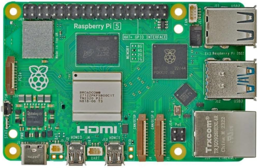
The Raspberry Pi 5 is the latest iteration of the popular series of single-board computers developed by the Raspberry Pi Foundation. Designed to be both affordable and powerful, the Raspberry Pi 5 can be used for a wide range of applications, from educational purposes to sophisticated electronic projects. Common uses include home automation, media centers, retro gaming consoles, and as a platform for learning programming and electronics.
Explore Projects Built with Raspberry Pi 5
Explore Projects Built with Raspberry Pi 5
Technical Specifications
General Specifications
- Processor: Quad-core CPU (details to be updated upon release)
- Memory: RAM (details to be updated upon release)
- Connectivity: Gigabit Ethernet, Wi-Fi, Bluetooth (details to be updated upon release)
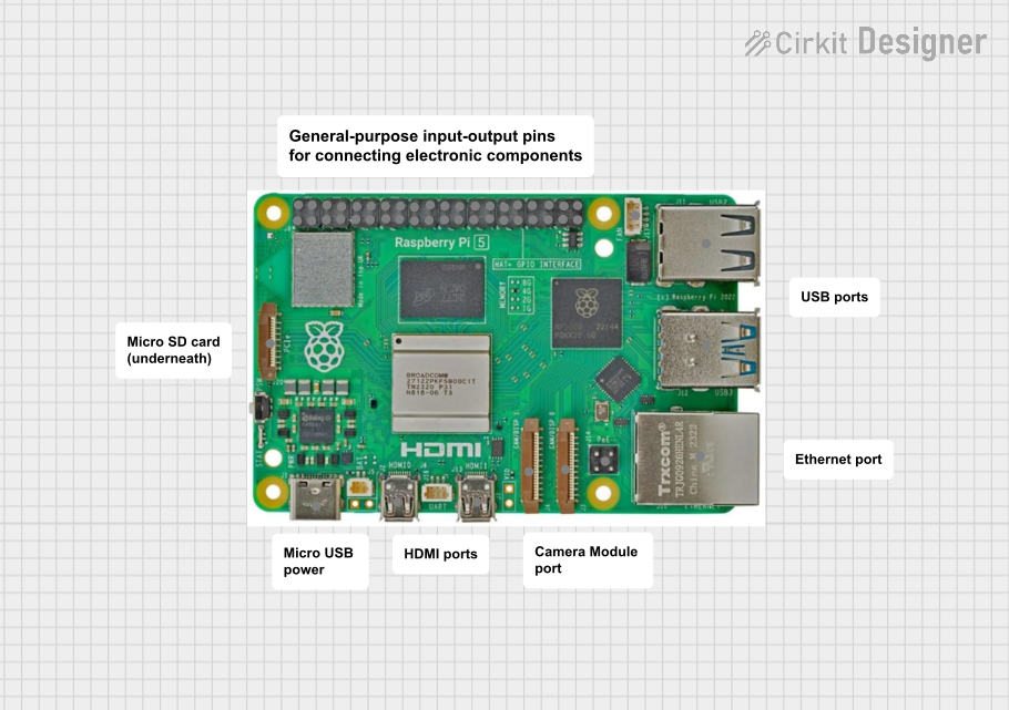
- Storage: MicroSD card slot for operating system and data storage
- USB Ports: Multiple USB ports for peripherals (details to be updated upon release)
- Video Output: HDMI (details to be updated upon release)
- GPIO: Standard 40-pin GPIO header
Pin Configuration
| Pin Number | Description | Notes |
|---|---|---|
| 1 | 3.3V Power | |
| 2 | 5V Power | |
| 3 | GPIO 2 (SDA) | I2C interface |
| 4 | 5V Power | |
| 5 | GPIO 3 (SCL) | I2C interface |
| 6 | Ground | |
| ... | ... | ... |
| 39 | Ground | |
| 40 | GPIO 21 (SPI0_MOSI) | SPI interface |
Note: The full pinout will be provided by the manufacturer upon release.
Usage Instructions
Setting Up the Raspberry Pi 5
- Prepare the MicroSD Card: Download the latest version of Raspberry Pi OS and write it to the MicroSD card using imaging software.
- Assemble the Hardware: Insert the MicroSD card into the slot, connect peripherals such as a keyboard, mouse, and monitor, and finally, power up the device using a compatible USB-C power supply.
- Initial Configuration: Follow the on-screen setup instructions to configure the Raspberry Pi OS, including setting up Wi-Fi, locale, and account details.
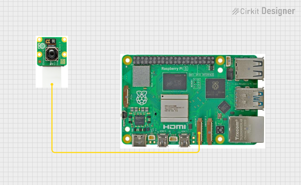
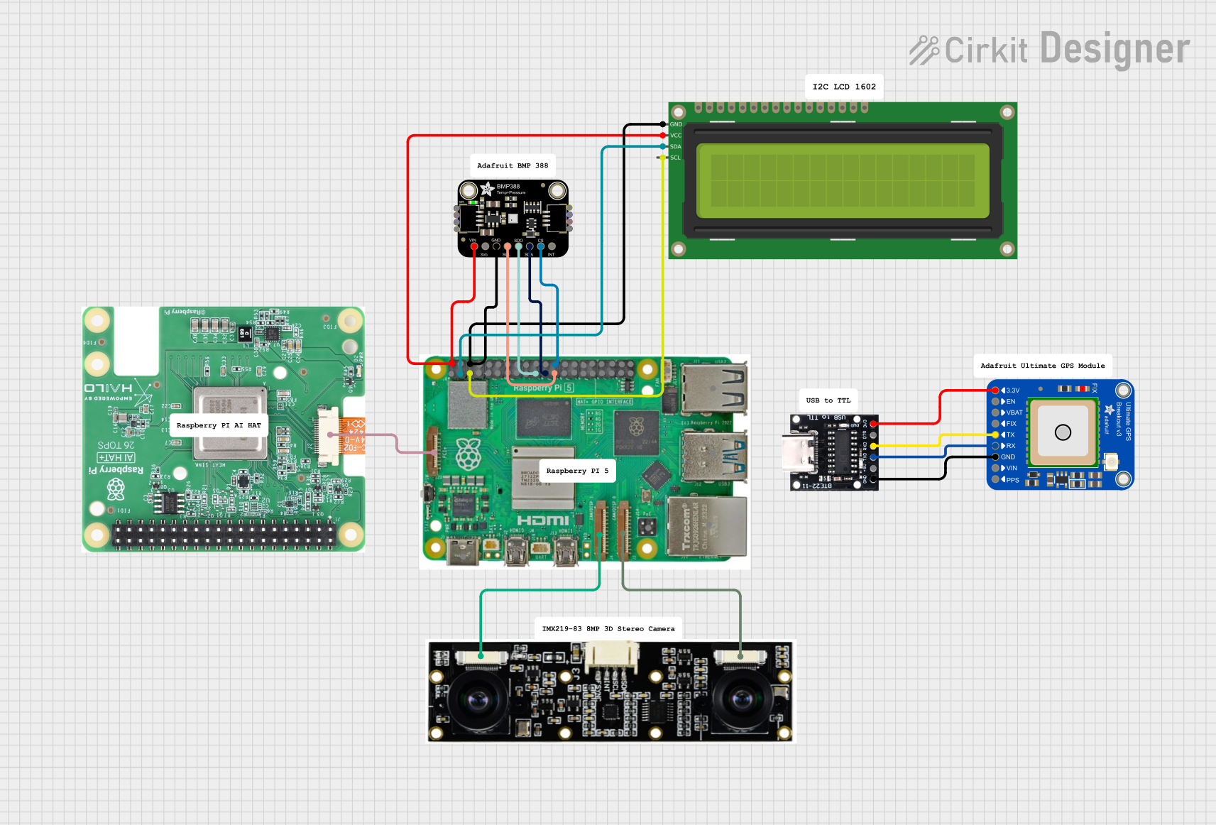
Interfacing with Electronic Components
- GPIO Usage: The GPIO pins can be used to interface with sensors, actuators, and other electronic components. Use resistors where necessary to protect the GPIO pins from overcurrent.
- I2C/SPI Devices: For connecting devices that use I2C or SPI communication protocols, ensure that these interfaces are enabled through the
raspi-configutility.
Best Practices
- Always power down the Raspberry Pi before connecting or disconnecting components to avoid damage.
- Use a proper power supply that meets the recommended specifications to ensure stable operation.
- Keep the Raspberry Pi in a case to protect it from static and physical damage.
Troubleshooting and FAQs
Common Issues
- Pi Does Not Boot: Ensure the MicroSD card is properly inserted and contains a valid OS image. Check the power supply and connections.
- Overheating: Make sure the Raspberry Pi has adequate ventilation. Consider using heat sinks or a fan if running intensive tasks.
- Network Issues: Verify Wi-Fi credentials and signal strength. For Ethernet, check the cable and router connection.
FAQs
- Can I use the Raspberry Pi 5 as a desktop computer? Yes, with a suitable OS, keyboard, mouse, and monitor, it can function as a basic desktop computer.
- What programming languages can I use with the Raspberry Pi 5? Common languages include Python, C++, Java, and Scratch, among others.
Note: This documentation will be updated with more specific troubleshooting tips and FAQs as more information about the Raspberry Pi 5 becomes available and as common issues are identified by the user community.
Example Code for Arduino UNO Interfacing
// Example code for interfacing Raspberry Pi 5 with an Arduino UNO
// This code is for the Arduino UNO to send sensor data to the Raspberry Pi 5 via serial communication.

#include <SoftwareSerial.h>

SoftwareSerial piSerial(10, 11); // RX, TX

void setup() {
  // Start the built-in serial port, for serial monitor
  Serial.begin(9600);
  // Start the software serial port, to communicate with the Raspberry Pi
  piSerial.begin(9600);
}

void loop() {
  // Read sensor data (example: a simple analog sensor connected to A0)
  int sensorValue = analogRead(A0);
  // Send the sensor data to the Raspberry Pi
  piSerial.println(sensorValue);
  // Wait for a second
  delay(1000);
}
Note: This code is for demonstration purposes. The actual implementation may vary based on the specific requirements of your project and the sensors used.
Remember to keep the code comments concise and within the 80-character line length limit. This ensures readability and maintainability of the code.