
How to Use Airspeed sensor: Examples, Pinouts, and Specs
 Design with Airspeed sensor in Cirkit Designer
Introduction
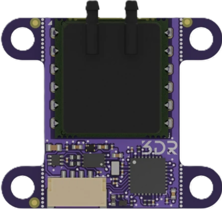
The Slim AUAV CAN Airspeed Sensor by 3DR is a precision device designed to measure the speed of an aircraft relative to the surrounding air. This sensor is commonly used in unmanned aerial vehicles (UAVs), drones, and other aircraft to provide accurate airspeed data, which is critical for navigation, stability, and performance optimization.
Explore Projects Built with Airspeed sensor
 Open Project in Cirkit Designer
 Open Project in Cirkit Designer
 Open Project in Cirkit Designer
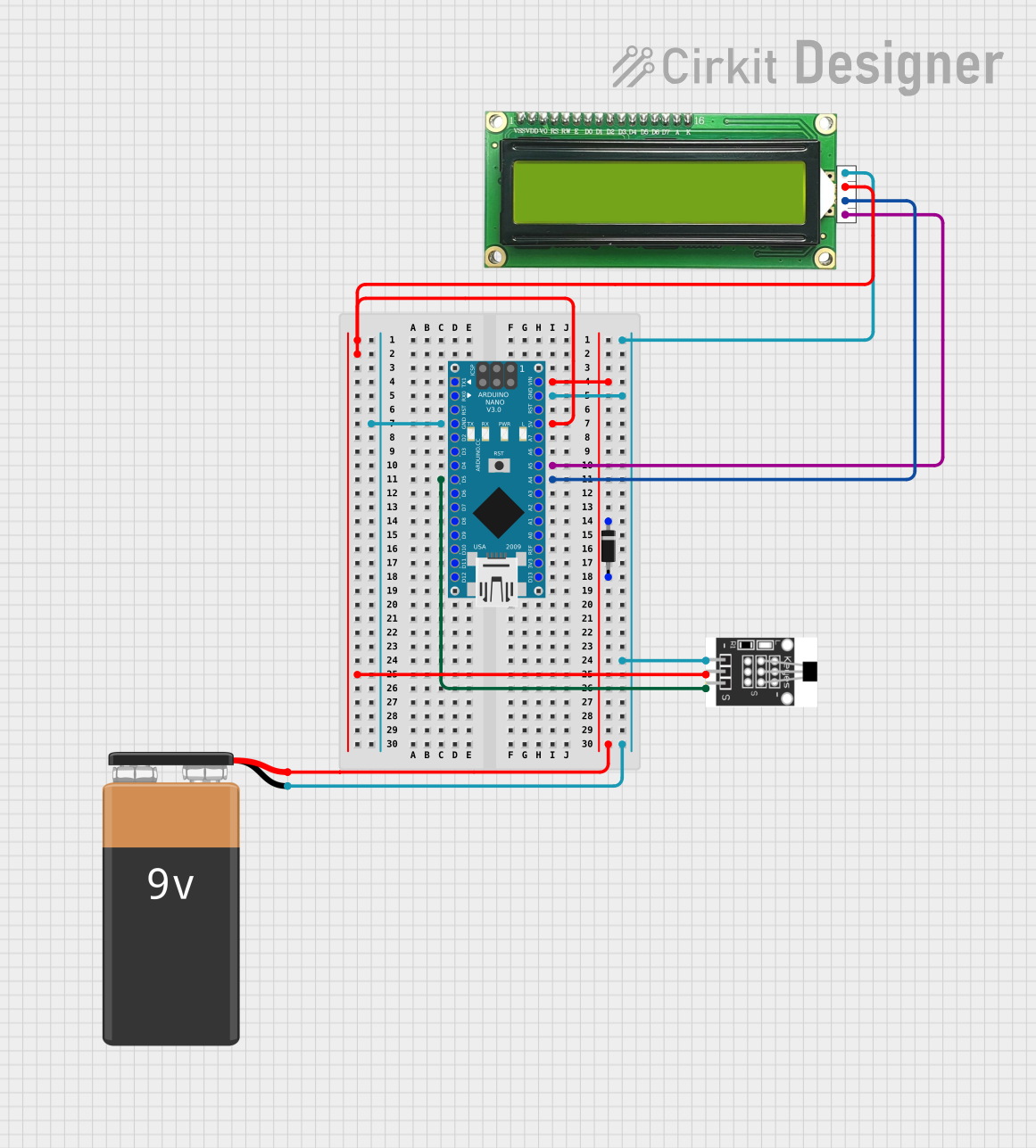 Open Project in Cirkit Designer
Explore Projects Built with Airspeed sensor
Open Project in Cirkit DesignerOpen Project in Cirkit DesignerOpen Project in Cirkit DesignerOpen Project in Cirkit DesignerCommon Applications and Use Cases
- Unmanned Aerial Vehicles (UAVs): Ensures stable flight and efficient navigation.
- Drones: Provides real-time airspeed data for autonomous flight control.
- Aircraft Systems: Used in experimental and small aircraft for airspeed monitoring.
- Weather Balloons: Measures wind speed and air movement at various altitudes.
- Research and Development: Ideal for testing aerodynamic performance in controlled environments.
Technical Specifications
The Slim AUAV CAN Airspeed Sensor is designed for high accuracy and reliability. Below are its key technical details:
Key Technical Details
| Parameter | Specification |
|---|---|
| Manufacturer | 3DR |
| Part ID | Slim AUAV CAN Airspeed Sensor |
| Measurement Range | 0 to 100 m/s |
| Operating Voltage | 4.5V to 5.5V |
| Communication Protocol | CAN (Controller Area Network) |
| Power Consumption | < 50 mA |
| Operating Temperature | -40°C to 85°C |
| Accuracy | ±1 m/s |
| Dimensions | 40mm x 20mm x 10mm |
| Weight | 10 grams |
Pin Configuration and Descriptions
The sensor uses a 4-pin JST-GH connector for interfacing. Below is the pinout:
| Pin Number | Pin Name | Description |
|---|---|---|
| 1 | VCC | Power supply input (4.5V to 5.5V) |
| 2 | GND | Ground |
| 3 | CAN_H | CAN bus high signal |
| 4 | CAN_L | CAN bus low signal |
Usage Instructions
How to Use the Component in a Circuit
- Power Supply: Connect the VCC pin to a regulated 5V power source and the GND pin to the ground of your system.
- CAN Bus Connection: Connect the CAN_H and CAN_L pins to the corresponding CAN bus lines of your system.
- Termination Resistor: Ensure that the CAN bus is properly terminated with a 120-ohm resistor at each end of the bus.
- Mounting: Secure the sensor in a location where it can measure airflow without obstruction.
- Data Reading: Use a microcontroller or flight controller with CAN bus support to read airspeed data.
Important Considerations and Best Practices
- Calibration: Perform a calibration procedure before use to ensure accurate readings.
- Orientation: Install the sensor in the correct orientation as specified in the datasheet.
- Environmental Factors: Avoid placing the sensor in areas with excessive vibration or turbulence.
- Firmware Compatibility: Ensure your flight controller or microcontroller firmware supports the Slim AUAV CAN Airspeed Sensor.
- Wiring: Use shielded cables for the CAN bus to minimize electromagnetic interference.
Example Code for Arduino UNO
The Slim AUAV CAN Airspeed Sensor uses the CAN protocol, which is not natively supported by the Arduino UNO. However, you can use an external CAN transceiver module (e.g., MCP2515) to interface with the sensor. Below is an example code snippet:
#include <SPI.h>
#include <mcp2515.h> // Library for MCP2515 CAN module

struct can_frame canMsg;
MCP2515 mcp2515(10); // CS pin connected to pin 10

void setup() {
  Serial.begin(9600);
  // Initialize MCP2515 CAN module
  if (mcp2515.begin(MCP_ANY, CAN_500KBPS, MCP_8MHZ) == CAN_OK) {
    Serial.println("CAN module initialized successfully");
  } else {
    Serial.println("Error initializing CAN module");
    while (1);
  }
  mcp2515.setMode(MCP_NORMAL); // Set CAN module to normal mode
}

void loop() {
  if (mcp2515.readMessage(&canMsg) == CAN_OK) {
    // Assuming airspeed data is sent in the first two bytes of the CAN message
    int airspeed = (canMsg.data[0] << 8) | canMsg.data[1];
    Serial.print("Airspeed: ");
    Serial.print(airspeed);
    Serial.println(" m/s");
  }
}
Note: This code assumes the use of an MCP2515 CAN module and a library such as "mcp2515.h". Ensure the CAN bus is properly terminated and configured for 500 kbps communication.
Troubleshooting and FAQs
Common Issues Users Might Face
No Data Output:
- Cause: Incorrect wiring or power supply issues.
- Solution: Verify all connections and ensure the sensor is receiving 5V power.
Inaccurate Readings:
- Cause: Sensor not calibrated or installed in a turbulent airflow area.
- Solution: Perform calibration and ensure proper sensor placement.
CAN Bus Communication Errors:
- Cause: Incorrect baud rate or missing termination resistors.
- Solution: Verify the CAN bus baud rate matches the sensor's configuration and ensure proper termination.
Interference on CAN Bus:
- Cause: Electromagnetic interference from nearby components.
- Solution: Use shielded cables and maintain proper grounding.
Solutions and Tips for Troubleshooting
- Check Firmware: Ensure your microcontroller or flight controller firmware supports the Slim AUAV CAN Airspeed Sensor.
- Inspect Wiring: Double-check all connections, especially the CAN_H and CAN_L lines.
- Monitor Power Supply: Use a stable and regulated 5V power source to avoid voltage fluctuations.
- Test with Known Good Components: If issues persist, test the sensor with a different CAN bus system to isolate the problem.
By following this documentation, users can effectively integrate and utilize the Slim AUAV CAN Airspeed Sensor in their projects.