Cirkit Designer
Your all-in-one circuit design IDE
Home /
Component Documentation
How to Use Terrarium: Examples, Pinouts, and Specs
Introduction
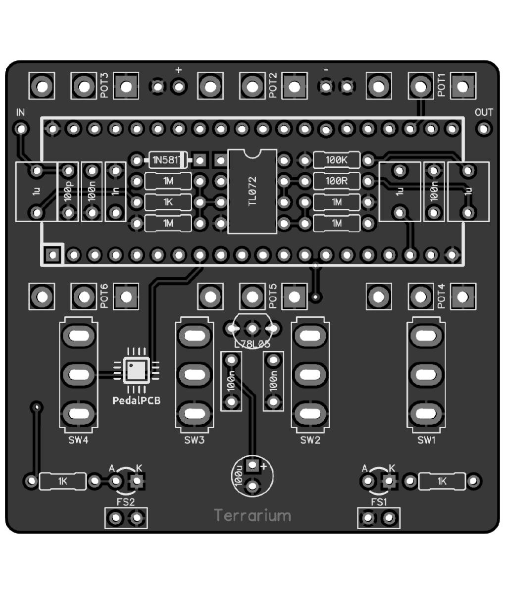
The Terrarium (PCB351) by PedalPCB is an electronic component designed to monitor and control the environmental conditions within a terrarium. This component is ideal for creating a small, self-sustaining ecosystem, often used for decorative or educational purposes. It integrates sensors and actuators to maintain optimal conditions for plant growth, such as temperature, humidity, and light levels.
Explore Projects Built with Terrarium
Arduino UNO R4 WiFi-Based Greenhouse Automation System
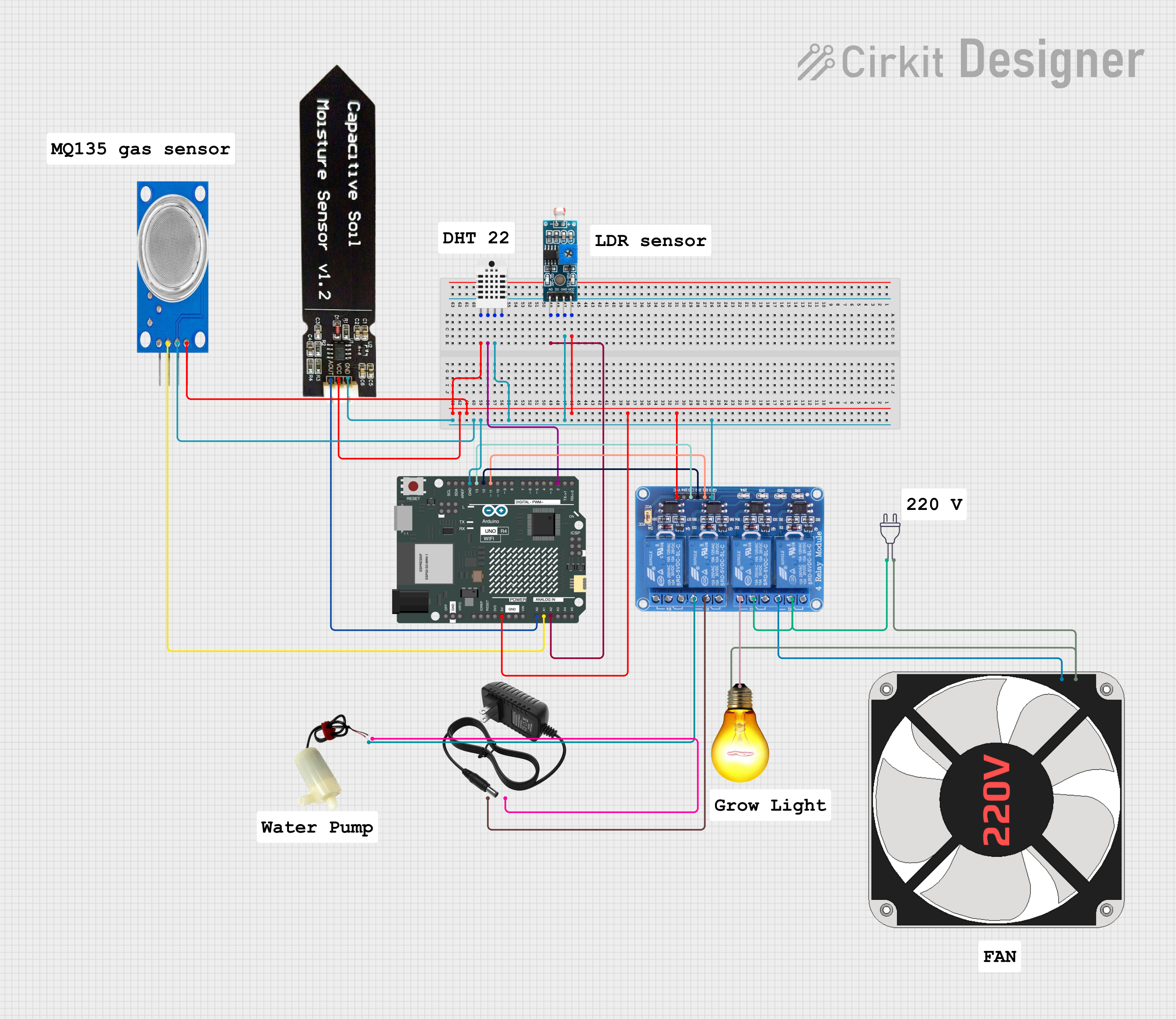
This circuit automates a greenhouse environment for a tomato plant using an Arduino UNO R4 WiFi. It reads data from sensors measuring humidity, temperature, soil moisture, air quality, and light intensity, and controls a relay module to manage a fan, an AC bulb, and a water pump to maintain optimal conditions.
ESP32-Based Smart Irrigation and Environmental Monitoring System
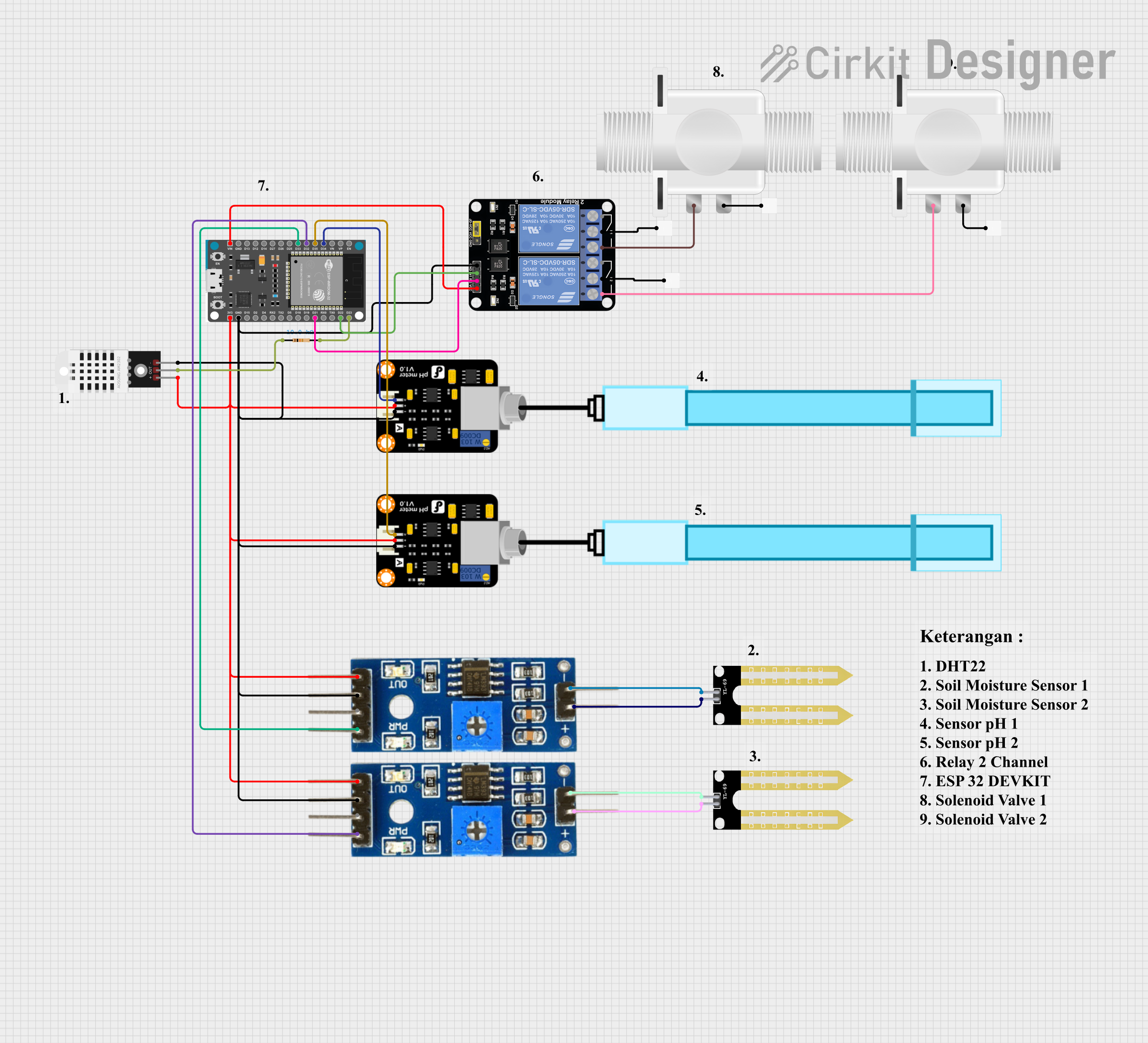
This is an automated environmental control system for plant growth that uses an ESP32 to monitor soil moisture and pH levels, and to manage irrigation through solenoid valves. The system aims to maintain optimal growing conditions by adjusting watering schedules based on sensor inputs.
ESP32-Based Smart Planting System with Wi-Fi Connectivity
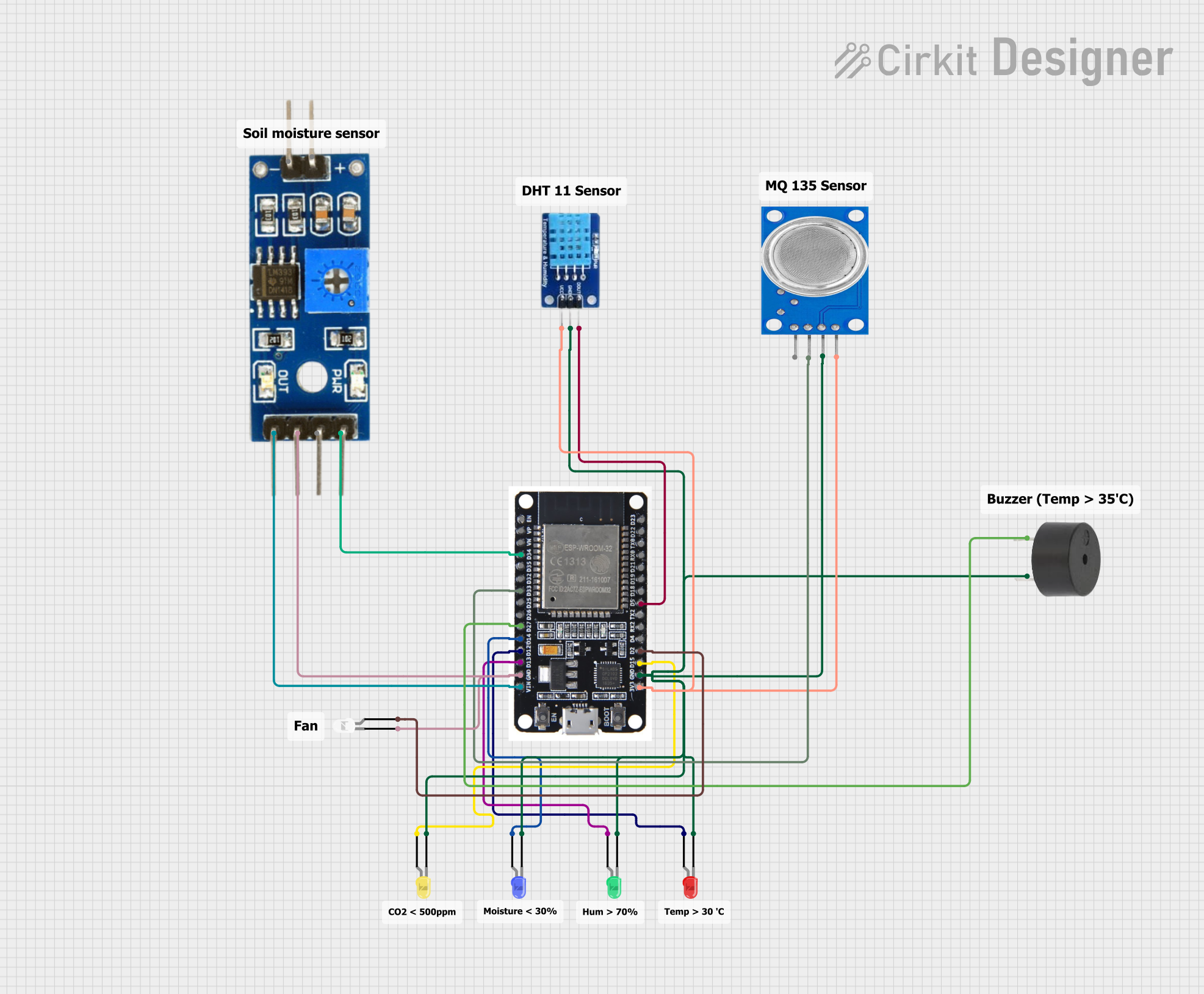
This circuit is a smart planting system using an ESP32 microcontroller to monitor and control environmental conditions. It includes sensors for temperature, humidity (DHT11), soil moisture, and air quality (MQ135), with visual indicators (LEDs) and an alert buzzer. The system also features a web interface for real-time data visualization and control.
Arduino Nano-Based Automated Greenhouse Control System with LCD Display
This circuit is designed for a greenhouse automation system. It features an Arduino Nano that controls a DHT11 sensor for temperature and humidity readings, a capacitive soil moisture sensor, a PIR sensor for motion detection, two pushbuttons for manual overrides, an LDR for light level sensing, a two-channel relay for controlling watering and lighting systems, and an I2C LCD screen for displaying sensor data. The system automates watering and lighting based on sensor inputs and allows manual control, with the LCD providing real-time feedback on environmental conditions.
Explore Projects Built with Terrarium
Arduino UNO R4 WiFi-Based Greenhouse Automation System
This circuit automates a greenhouse environment for a tomato plant using an Arduino UNO R4 WiFi. It reads data from sensors measuring humidity, temperature, soil moisture, air quality, and light intensity, and controls a relay module to manage a fan, an AC bulb, and a water pump to maintain optimal conditions.
ESP32-Based Smart Irrigation and Environmental Monitoring System
This is an automated environmental control system for plant growth that uses an ESP32 to monitor soil moisture and pH levels, and to manage irrigation through solenoid valves. The system aims to maintain optimal growing conditions by adjusting watering schedules based on sensor inputs.
ESP32-Based Smart Planting System with Wi-Fi Connectivity
This circuit is a smart planting system using an ESP32 microcontroller to monitor and control environmental conditions. It includes sensors for temperature, humidity (DHT11), soil moisture, and air quality (MQ135), with visual indicators (LEDs) and an alert buzzer. The system also features a web interface for real-time data visualization and control.
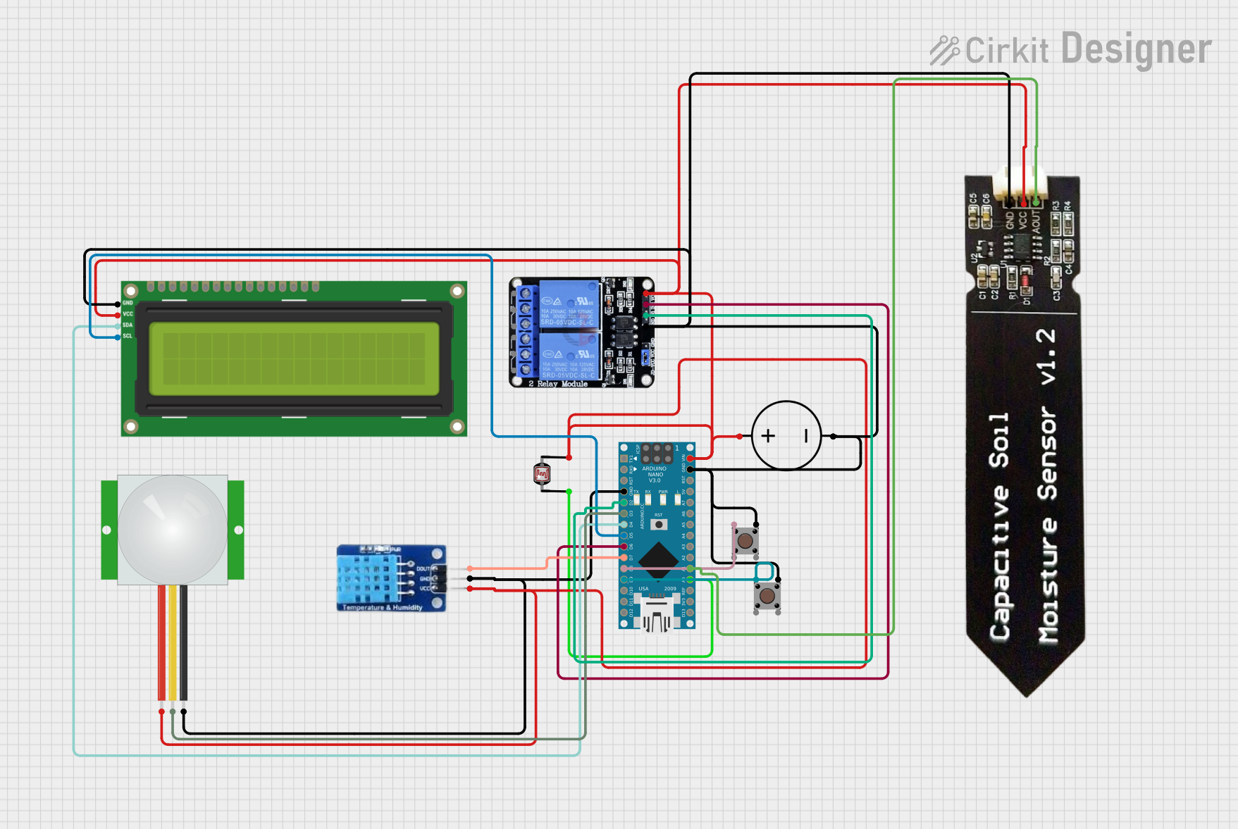
Arduino Nano-Based Automated Greenhouse Control System with LCD Display
This circuit is designed for a greenhouse automation system. It features an Arduino Nano that controls a DHT11 sensor for temperature and humidity readings, a capacitive soil moisture sensor, a PIR sensor for motion detection, two pushbuttons for manual overrides, an LDR for light level sensing, a two-channel relay for controlling watering and lighting systems, and an I2C LCD screen for displaying sensor data. The system automates watering and lighting based on sensor inputs and allows manual control, with the LCD providing real-time feedback on environmental conditions.
Common Applications and Use Cases
- Home Decor: Enhance the aesthetic appeal of living spaces with a self-sustaining ecosystem.
- Educational Projects: Teach students about ecosystems, plant biology, and environmental science.
- Hobbyist Projects: Ideal for DIY enthusiasts interested in creating and maintaining terrariums.
- Research: Useful in botanical and ecological research to study plant growth under controlled conditions.
Technical Specifications
Key Technical Details
| Parameter | Value |
|---|---|
| Operating Voltage | 5V DC |
| Current Consumption | 100mA |
| Power Rating | 0.5W |
| Temperature Range | 0°C to 50°C |
| Humidity Range | 20% to 90% RH |
| Light Sensor Range | 0 to 1000 lux |
Pin Configuration and Descriptions
| Pin No. | Pin Name | Description |
|---|---|---|
| 1 | VCC | Power supply (5V DC) |
| 2 | GND | Ground |
| 3 | TEMP | Temperature sensor output |
| 4 | HUM | Humidity sensor output |
| 5 | LIGHT | Light sensor output |
| 6 | CTRL | Control signal for actuators (e.g., fans, lights) |
Usage Instructions
How to Use the Component in a Circuit
- Power Supply: Connect the VCC pin to a 5V DC power source and the GND pin to the ground.
- Sensor Outputs: Connect the TEMP, HUM, and LIGHT pins to the corresponding analog input pins on a microcontroller (e.g., Arduino UNO).
- Control Signal: Connect the CTRL pin to a digital output pin on the microcontroller to control actuators like fans or lights.
Important Considerations and Best Practices
- Power Supply: Ensure a stable 5V DC power supply to avoid fluctuations that could affect sensor readings.
- Sensor Placement: Place the sensors in locations within the terrarium where they can accurately measure the environmental conditions.
- Calibration: Periodically calibrate the sensors to maintain accuracy.
- Actuator Control: Use appropriate drivers or relays to control high-power actuators.
Example Code for Arduino UNO
// Include necessary libraries
#include <DHT.h>
#include <Wire.h>

// Define pin connections
#define TEMP_PIN A0
#define HUM_PIN A1
#define LIGHT_PIN A2
#define CTRL_PIN 7

// Initialize DHT sensor
DHT dht(TEMP_PIN, DHT11);

void setup() {
  // Initialize serial communication
  Serial.begin(9600);

  // Initialize sensor pins
  pinMode(TEMP_PIN, INPUT);
  pinMode(HUM_PIN, INPUT);
  pinMode(LIGHT_PIN, INPUT);
  pinMode(CTRL_PIN, OUTPUT);

  // Start DHT sensor
  dht.begin();
}

void loop() {
  // Read temperature and humidity
  float temperature = dht.readTemperature();
  float humidity = dht.readHumidity();

  // Read light level
  int lightLevel = analogRead(LIGHT_PIN);

  // Print sensor values to serial monitor
  Serial.print("Temperature: ");
  Serial.print(temperature);
  Serial.print(" °C, Humidity: ");
  Serial.print(humidity);
  Serial.print(" %, Light Level: ");
  Serial.println(lightLevel);

  // Control actuator based on sensor values
  if (temperature > 30 || humidity < 40 || lightLevel < 200) {
    digitalWrite(CTRL_PIN, HIGH); // Turn on actuator
  } else {
    digitalWrite(CTRL_PIN, LOW);  // Turn off actuator
  }

  // Wait for 2 seconds before next reading
  delay(2000);
}
Troubleshooting and FAQs
Common Issues Users Might Face
Inaccurate Sensor Readings:
- Solution: Ensure sensors are properly calibrated and placed in optimal locations within the terrarium.
Power Supply Issues:
- Solution: Use a stable 5V DC power source and check connections for any loose wires.
Actuator Not Responding:
- Solution: Verify the control signal from the microcontroller and ensure the actuator driver or relay is functioning correctly.
Solutions and Tips for Troubleshooting
- Check Connections: Ensure all connections are secure and correctly placed.
- Monitor Serial Output: Use the serial monitor to debug and verify sensor readings and control signals.
- Use External Libraries: Utilize libraries like DHT for temperature and humidity sensors to simplify code and improve accuracy.
By following this documentation, users can effectively integrate the Terrarium (PCB351) into their projects, ensuring optimal performance and reliability.