How to Use esp32 30 pin: Examples, Pinouts, and Specs
Introduction
The ESP32 Development Board 30 Pin, manufactured by Espressif Systems, is a powerful and versatile microcontroller designed for IoT and embedded systems applications. It features built-in Wi-Fi and Bluetooth capabilities, making it ideal for wireless communication projects. With 30 GPIO pins, the ESP32 offers extensive input/output functionality, enabling developers to interface with a wide range of sensors, actuators, and other peripherals.
Explore Projects Built with esp32 30 pin


Explore Projects Built with esp32 30 pin
Common Applications
- IoT devices and smart home automation
- Wireless sensor networks
- Wearable technology
- Robotics and automation systems
- Data logging and remote monitoring
- Prototyping and educational projects
Technical Specifications
The ESP32 Development Board 30 Pin is built around the ESP32 SoC, which integrates a dual-core processor, wireless communication modules, and a variety of peripherals.
Key Technical Details
| Specification | Value |
|---|---|
| Manufacturer | Espressif Systems |
| Part ID | ESP32 Development Board 30 Pin |
| Processor | Dual-core Xtensa® 32-bit LX6 |
| Clock Speed | Up to 240 MHz |
| Flash Memory | 4 MB (varies by board version) |
| SRAM | 520 KB |
| Wi-Fi | 802.11 b/g/n |
| Bluetooth | v4.2 BR/EDR and BLE |
| Operating Voltage | 3.3V |
| Input Voltage (VIN) | 5V (via USB or VIN pin) |
| GPIO Pins | 30 |
| ADC Channels | 18 (12-bit resolution) |
| DAC Channels | 2 |
| PWM Outputs | Multiple |
| Communication Interfaces | UART, SPI, I2C, I2S, CAN, Ethernet MAC |
| Power Consumption | Ultra-low power modes available |
| Dimensions | ~51mm x 25mm |
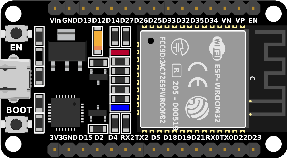
Pin Configuration and Descriptions
The ESP32 30 Pin board has a total of 30 GPIO pins, each with multiple functions. Below is a summary of the pin configuration:
| Pin Number | Pin Name | Functionality |
|---|---|---|
| 1 | EN | Enable pin (active high, resets the chip when pulled low) |
| 2 | IO0 | GPIO0, used for boot mode selection, can also be used as a general GPIO |
| 3 | IO1 (TX0) | GPIO1, UART0 TX (default serial communication pin) |
| 4 | IO3 (RX0) | GPIO3, UART0 RX (default serial communication pin) |
| 5 | IO4 | GPIO4, supports PWM, ADC, and other functions |
| 6 | IO5 | GPIO5, supports PWM, ADC, and other functions |
| ... | ... | ... (remaining pins follow similar descriptions) |
| 30 | GND | Ground pin |
Note: Some GPIO pins have specific restrictions or are reserved for internal functions. Refer to the ESP32 datasheet for detailed pin multiplexing information.
Usage Instructions
How to Use the ESP32 in a Circuit
Powering the Board:
- Connect the ESP32 to a 5V power source via the USB port or the VIN pin. The onboard voltage regulator will step down the voltage to 3.3V for the ESP32.
- Ensure the power supply can provide sufficient current (at least 500mA) for stable operation.
Programming the ESP32:
- Install the Arduino IDE and add the ESP32 board support package via the Board Manager.
- Connect the ESP32 to your computer using a USB cable.
- Select the correct board (
ESP32 Dev Module) and port in the Arduino IDE. - Write your code and upload it to the ESP32.
Connecting Peripherals:
- Use the GPIO pins to interface with sensors, actuators, and other devices.
- Ensure that the voltage levels of connected peripherals are compatible with the ESP32's 3.3V logic.
Example Code: Blinking an LED
The following example demonstrates how to blink an LED connected to GPIO2 of the ESP32:
// Define the GPIO pin for the LED
const int ledPin = 2;

void setup() {
  // Set the LED pin as an output
  pinMode(ledPin, OUTPUT);
}

void loop() {
  // Turn the LED on
  digitalWrite(ledPin, HIGH);
  delay(1000); // Wait for 1 second

  // Turn the LED off
  digitalWrite(ledPin, LOW);
  delay(1000); // Wait for 1 second
}
Important Considerations
- Voltage Levels: The ESP32 operates at 3.3V logic. Avoid connecting 5V signals directly to its GPIO pins.
- Boot Mode: GPIO0 must be pulled low during boot to enter programming mode.
- Power Supply: Use a stable power source to prevent unexpected resets or malfunctions.
Troubleshooting and FAQs
Common Issues
ESP32 Not Detected by Computer:
- Ensure the USB cable is functional and supports data transfer.
- Install the correct USB-to-serial driver for your operating system.
Upload Fails with "Failed to Connect" Error:
- Press and hold the "BOOT" button on the ESP32 while uploading the code.
- Check the connection between the ESP32 and your computer.
Wi-Fi Connection Issues:
- Verify the SSID and password in your code.
- Ensure the Wi-Fi network is within range and not using unsupported security protocols.
GPIO Pin Not Working:
- Check if the pin is reserved for internal functions (e.g., GPIO6–GPIO11 are used for flash memory).
- Verify that the pin is not being used by another peripheral.
FAQs
Q: Can I power the ESP32 with a 3.3V source directly?
A: Yes, you can power the ESP32 directly via the 3.3V pin, but ensure the source is stable and can supply sufficient current.
Q: How do I reset the ESP32?
A: Press the "EN" button on the board to reset the ESP32.
Q: Can the ESP32 handle 5V logic on its GPIO pins?
A: No, the ESP32 operates at 3.3V logic. Use a level shifter if interfacing with 5V devices.
Q: How do I use the ESP32's Bluetooth functionality?
A: The ESP32 supports both Bluetooth Classic and BLE. Use the BluetoothSerial or BLE libraries in the Arduino IDE to implement Bluetooth functionality.
By following this documentation, you can effectively utilize the ESP32 Development Board 30 Pin for your projects.