How to Use SparkFun Qwiic Thermocouple Amplifier MCP9600 (Screw Terminals): Examples, Pinouts, and Specs
Introduction
The SparkFun Qwiic Thermocouple Amplifier MCP9600 (Screw Terminals) is a sophisticated electronic component designed for high-precision temperature measurements. This device utilizes the MCP9600 chip to convert thermocouple EMF to temperature readings, facilitating the monitoring of high-temperature environments. It is commonly used in applications such as industrial temperature control, consumer appliances, and thermal monitoring systems.
Explore Projects Built with SparkFun Qwiic Thermocouple Amplifier MCP9600 (Screw Terminals)
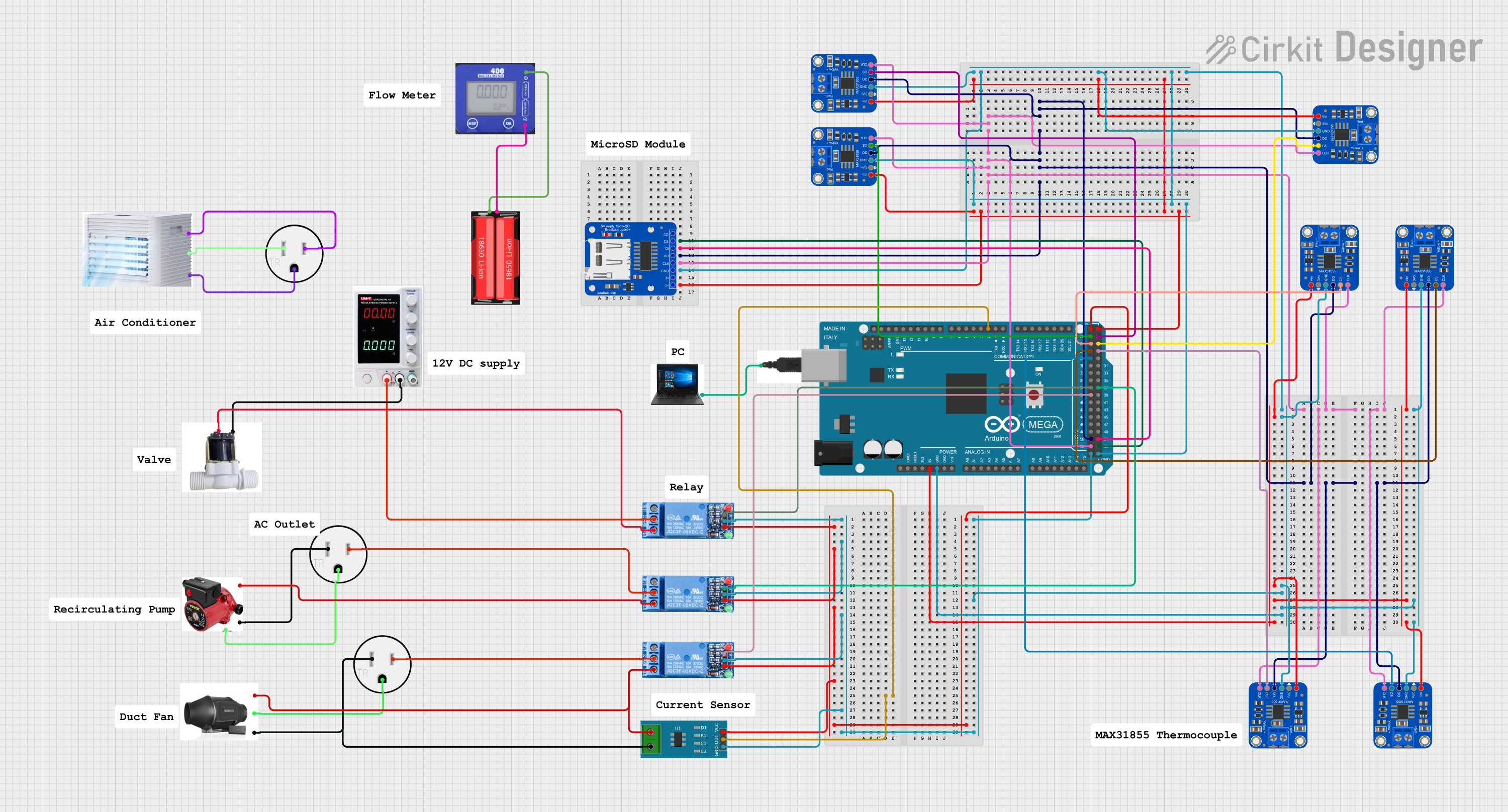
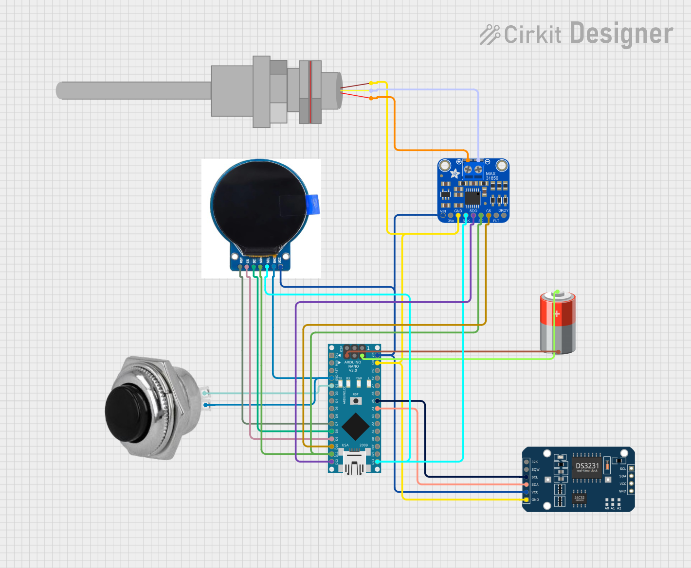

Explore Projects Built with SparkFun Qwiic Thermocouple Amplifier MCP9600 (Screw Terminals)
Technical Specifications
Key Features
- Thermocouple Type: K-type
- Input Voltage (VDD): 2.7V - 5.5V
- Temperature Range (Thermocouple): -200°C to +1372°C
- Temperature Range (Ambient): -40°C to +125°C
- Temperature Resolution: 0.0625°C
- Interface: I2C (Qwiic Connect System)
- I2C Addresses: 0x60 (default), 0x67 (alternative)
- Operating Current: 1mA (typical)
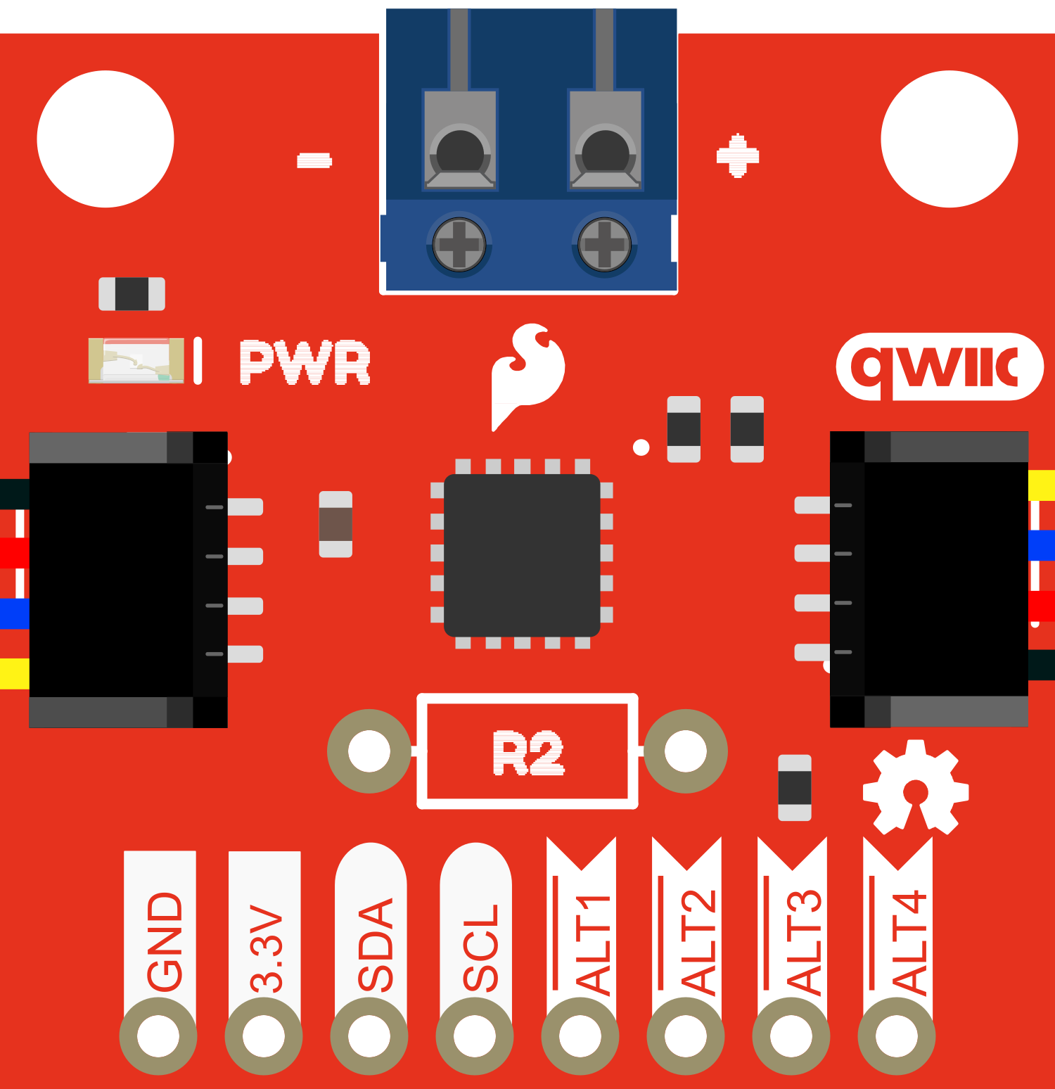
Pin Configuration and Descriptions
| Pin Name | Description |
|---|---|
| GND | Ground connection |
| VDD | Power supply (2.7V - 5.5V) |
| SDA | I2C Data Line |
| SCL | I2C Clock Line |
| ALERT | Alert pin for interrupt output |
| 3V3 | 3.3V output from the onboard voltage regulator |
| T+ | Thermocouple positive connection |
| T- | Thermocouple negative connection |
Usage Instructions
Connecting the Thermocouple
- Connect the K-type thermocouple leads to the T+ and T- screw terminals, ensuring correct polarity.
- Connect the VDD pin to a 2.7V - 5.5V power source.
- Connect the GND pin to the ground of your power source.
- Interface with the device using the I2C protocol via the SDA and SCL pins.
Best Practices
- Use twisted pair wires for the thermocouple to minimize electrical noise.
- Keep the thermocouple and amplifier away from high-temperature sources to avoid damage.
- Ensure that the screw terminals are securely fastened to maintain a good connection.
- Use the onboard 3V3 pin if you need a 3.3V power source for other components in your circuit.
Example Code for Arduino UNO
#include <Wire.h>
#include <SparkFun_MCP9600.h>

MCP9600 tempSensor;

void setup() {
  Wire.begin(); // Join I2C bus
  Serial.begin(9600); // Start serial communication at 9600 baud

  if (tempSensor.begin() == false) {
    Serial.println("MCP9600 not detected. Please check your connections.");
    while (1);
  }
}

void loop() {
  Serial.print("Ambient: ");
  Serial.print(tempSensor.getAmbientTempC(), 4); // Print ambient temperature
  Serial.print(" C, Thermocouple: ");
  Serial.print(tempSensor.getThermocoupleTempC(), 4); // Print thermocouple temperature
  Serial.println(" C");
  delay(1000); // Wait 1 second before next reading
}
Troubleshooting and FAQs
Common Issues
- No Temperature Readings: Ensure that the thermocouple is properly connected to the T+ and T- terminals and that the polarity is correct.
- Inaccurate Readings: Check for any sources of electromagnetic interference near the thermocouple or amplifier and use twisted pair wires for the thermocouple.
- I2C Communication Failure: Verify that the SDA and SCL lines are connected correctly and that there are pull-up resistors on the I2C bus if needed.
FAQs
Q: Can I use a different type of thermocouple with this amplifier? A: The MCP9600 is designed specifically for K-type thermocouples, so using other types is not recommended.
Q: How do I change the I2C address? A: The I2C address can be changed by altering the ADR0 jumper on the board. Please refer to the SparkFun MCP9600 datasheet for more details.
Q: What is the maximum length for the thermocouple wires? A: The maximum length depends on the application and environment, but it is generally recommended to keep the wires as short as possible to minimize potential interference and signal loss.
For further assistance, consult the SparkFun Qwiic Thermocouple Amplifier MCP9600 datasheet or contact technical support.