How to Use DVC6200 Positioner: Examples, Pinouts, and Specs
Introduction
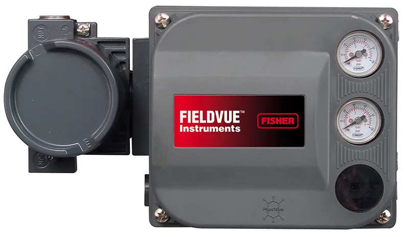
The DVC6200 Positioner is a digital valve controller designed for precise control of valve position in industrial applications. It ensures accurate and reliable operation of control valves, making it an essential component in process automation systems. The DVC6200 features advanced diagnostics, seamless integration with control systems, and enhanced performance to improve process efficiency and reduce downtime.
Explore Projects Built with DVC6200 Positioner
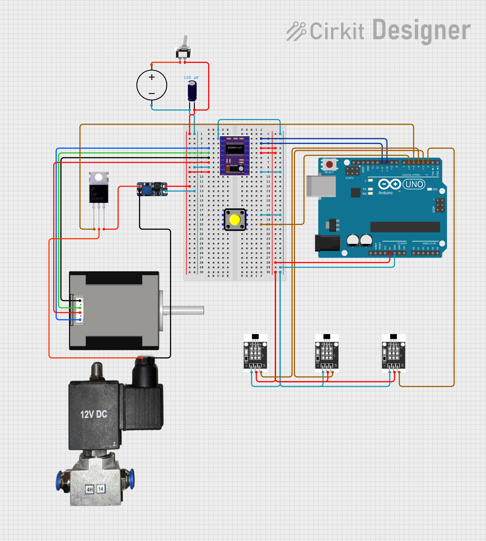
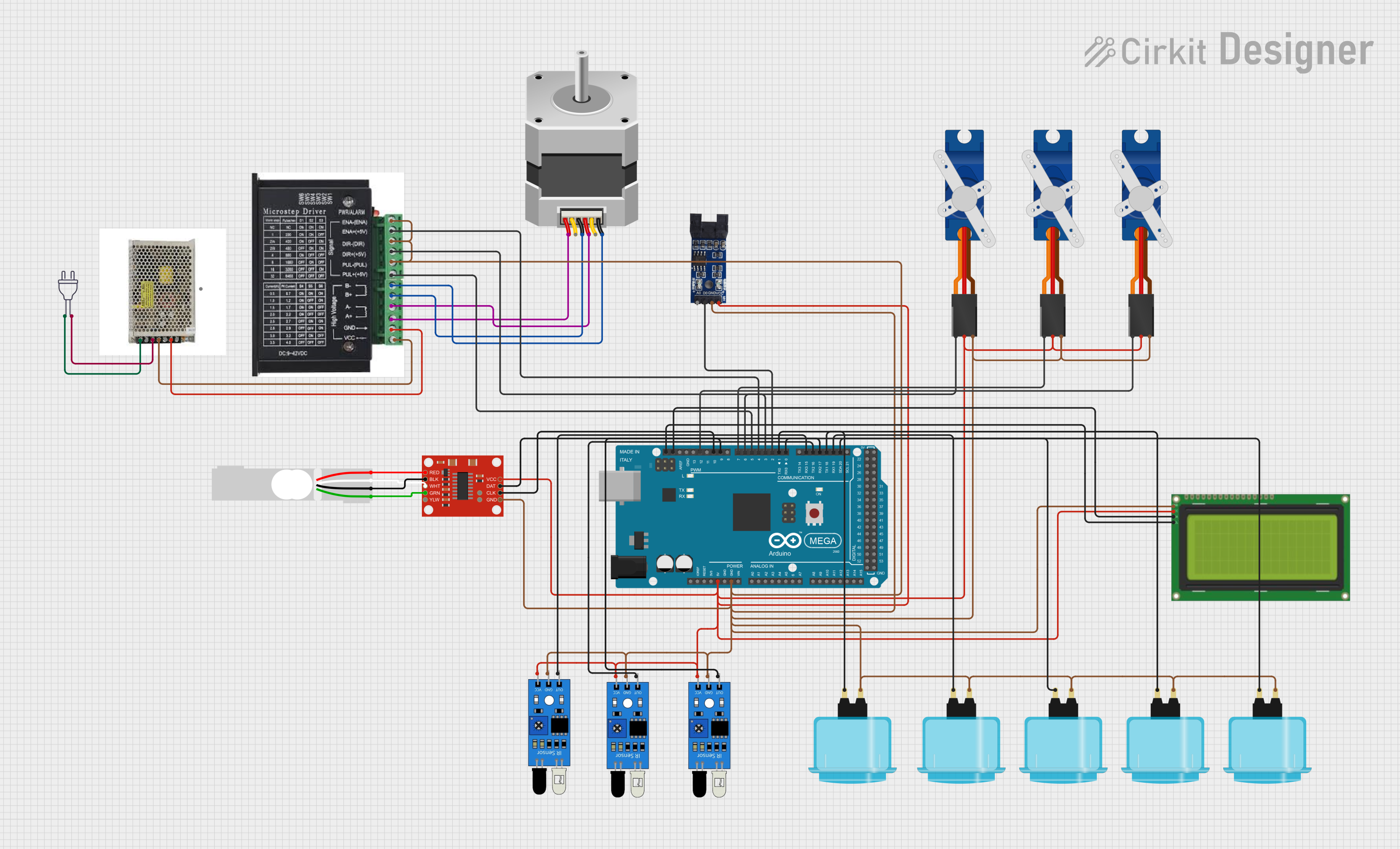


Explore Projects Built with DVC6200 Positioner
Common Applications and Use Cases
- Process Control: Used in industries such as oil and gas, chemical processing, and power generation to regulate fluid flow.
- Valve Diagnostics: Provides real-time feedback on valve health and performance.
- Automation Systems: Integrates with distributed control systems (DCS) and programmable logic controllers (PLC) for automated operations.
- Energy Efficiency: Optimizes valve performance to reduce energy consumption in industrial processes.
Technical Specifications
Key Technical Details
| Parameter | Specification |
|---|---|
| Power Supply | 12–30 VDC |
| Input Signal | 4–20 mA DC |
| Communication Protocols | HART, FOUNDATION Fieldbus, or PROFIBUS |
| Operating Temperature Range | -40°C to +85°C (-40°F to +185°F) |
| Valve Travel Range | 0.5 to 32 inches (12.7 to 813 mm) |
| Accuracy | ±0.5% of full scale |
| Enclosure Rating | IP66/NEMA 4X |
| Diagnostics | Advanced valve diagnostics, including travel deviation and friction monitoring |
Pin Configuration and Descriptions
The DVC6200 Positioner typically connects to a control system or power source via a terminal block. Below is a general description of the pin configuration:
| Pin Number | Label | Description |
|---|---|---|
| 1 | +24V | Positive terminal for 24 VDC power supply |
| 2 | GND | Ground terminal |
| 3 | 4–20 mA IN | Input signal for valve position control |
| 4 | HART+ | HART communication positive terminal |
| 5 | HART- | HART communication negative terminal |
| 6 | Feedback+ | Positive terminal for position feedback signal |
| 7 | Feedback- | Negative terminal for position feedback signal |
Note: Pin configurations may vary depending on the specific model or manufacturer. Always refer to the official datasheet for your device.
Usage Instructions
How to Use the DVC6200 Positioner in a Circuit
- Power Connection: Connect the +24V and GND terminals to a 24 VDC power supply.
- Signal Input: Connect the 4–20 mA input signal from the control system to the corresponding terminals.
- HART Communication: If using HART, connect the HART+ and HART- terminals to the HART communicator or control system.
- Valve Mounting: Securely mount the positioner to the valve actuator using the appropriate mounting kit.
- Calibration: Use the built-in calibration feature to set the zero and span for the valve travel.
- Diagnostics: Enable diagnostics via the control system or HART communicator to monitor valve performance.
Important Considerations and Best Practices
- Power Supply: Ensure the power supply voltage is within the specified range (12–30 VDC).
- Signal Integrity: Use shielded cables for the 4–20 mA signal to minimize electrical noise.
- Environmental Protection: Verify that the enclosure rating (IP66/NEMA 4X) is suitable for the installation environment.
- Regular Maintenance: Periodically check for wear and tear on the valve and positioner to ensure optimal performance.
- HART Configuration: Use a HART communicator to configure advanced settings and access diagnostic data.
Example: Connecting to an Arduino UNO
While the DVC6200 Positioner is typically used in industrial systems, it can be interfaced with an Arduino UNO for testing or educational purposes. Below is an example of how to read the 4–20 mA signal using an Arduino:
// Example code to read a 4–20 mA signal from the DVC6200 Positioner
// Requires a 250-ohm resistor to convert the current signal to a voltage signal

const int analogPin = A0; // Analog pin connected to the 250-ohm resistor
float currentSignal;      // Variable to store the current in mA

void setup() {
  Serial.begin(9600); // Initialize serial communication
}

void loop() {
  int analogValue = analogRead(analogPin); // Read the analog input
  float voltage = (analogValue / 1023.0) * 5.0; // Convert to voltage (0–5V)

  // Calculate the current in mA (Ohm's Law: I = V / R)
  currentSignal = (voltage / 250.0) * 1000.0;

  // Print the current signal to the serial monitor
  Serial.print("Current Signal: ");
  Serial.print(currentSignal);
  Serial.println(" mA");

  delay(1000); // Wait for 1 second before the next reading
}
Note: This example assumes the use of a 250-ohm resistor to convert the 4–20 mA signal to a 1–5 V voltage range, which is compatible with the Arduino's analog input.
Troubleshooting and FAQs
Common Issues and Solutions
| Issue | Possible Cause | Solution |
|---|---|---|
| No response from the positioner | Power supply not connected or incorrect voltage | Verify the power supply connections and ensure the voltage is within range. |
| Erratic valve movement | Electrical noise or signal interference | Use shielded cables and ensure proper grounding. |
| HART communication not working | Incorrect wiring or configuration | Check the HART wiring and verify the configuration settings. |
| Inaccurate valve positioning | Calibration not performed | Perform a zero and span calibration using the built-in tools. |
| Diagnostic alerts for high friction | Valve or actuator issues | Inspect the valve and actuator for mechanical wear or obstructions. |
FAQs
Can the DVC6200 Positioner be used in hazardous environments?
- Yes, certain models are certified for use in hazardous areas. Check the product datasheet for specific certifications.
How do I access diagnostic data?
- Diagnostic data can be accessed using a HART communicator, DCS, or compatible software.
What is the maximum cable length for the 4–20 mA signal?
- The maximum cable length depends on the cable resistance and power supply voltage. Refer to the installation manual for detailed guidelines.
Can I use the DVC6200 with a pneumatic actuator?
- Yes, the DVC6200 is compatible with both pneumatic and electric actuators.
What maintenance is required for the DVC6200?
- Regularly inspect the device for physical damage, clean the enclosure, and check the valve and actuator for proper operation.
By following this documentation, users can effectively integrate and maintain the DVC6200 Positioner in their industrial systems.