How to Use DIP - 14 pins: Examples, Pinouts, and Specs
Introduction
The DIP-14 (Dual In-line Package with 14 pins) is a widely used packaging for integrated circuits (ICs). This package features two parallel rows of electrical connecting pins, with seven pins on each side. The DIP-14 package is designed for through-hole mounting on printed circuit boards (PCBs) and is commonly used in a variety of electronic devices due to its ease of handling and soldering.
Explore Projects Built with DIP - 14 pins

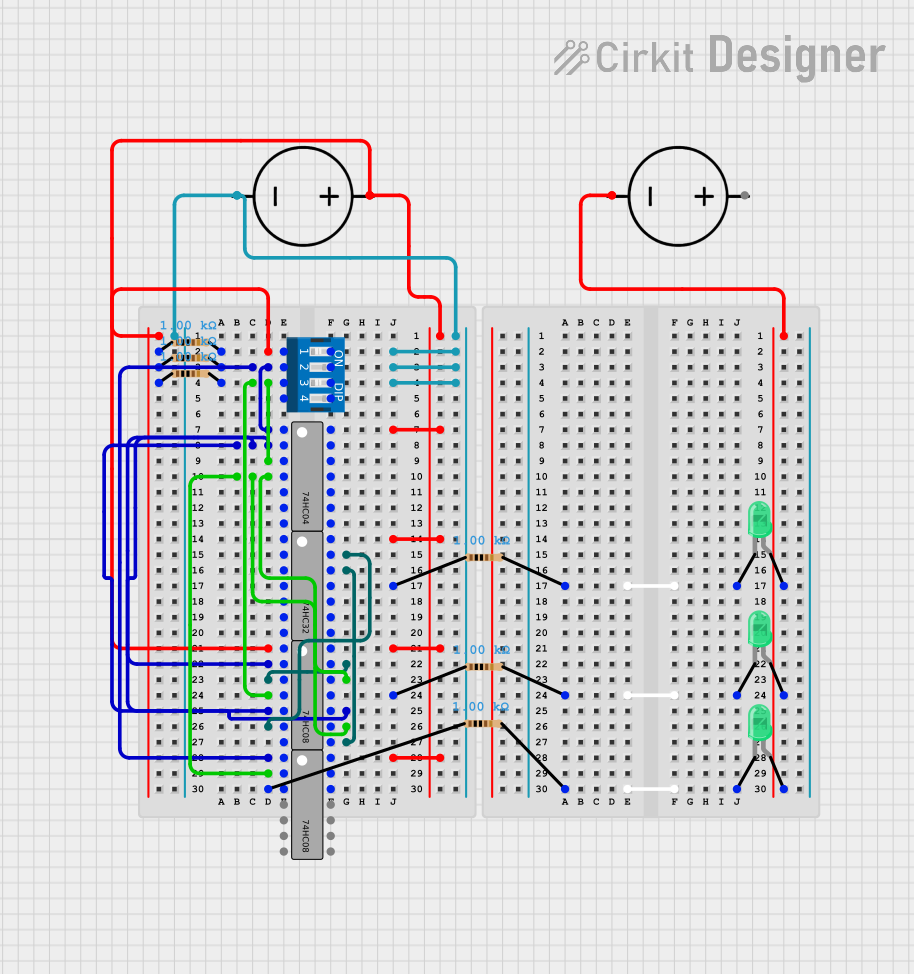
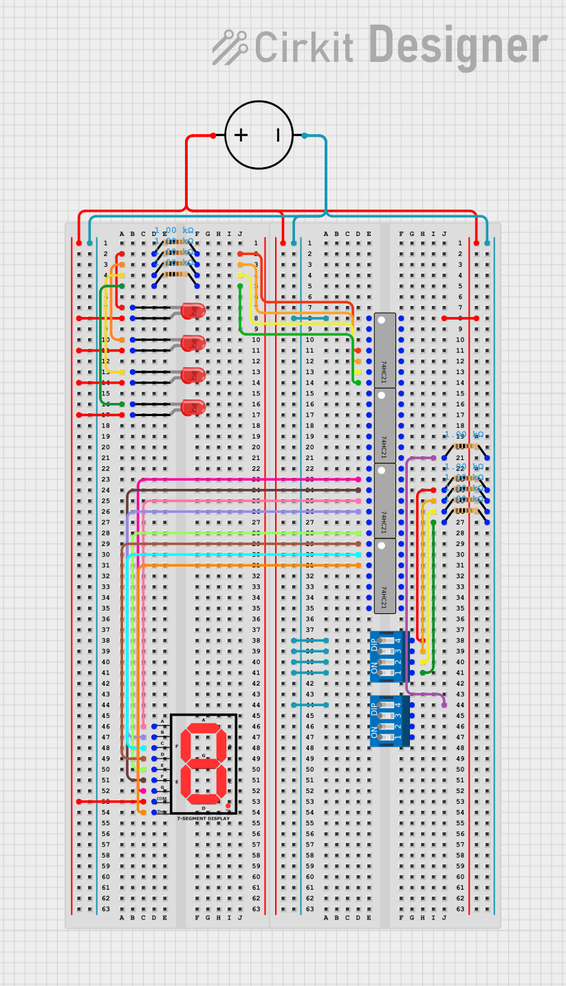

Explore Projects Built with DIP - 14 pins
Common Applications and Use Cases
- Digital and analog circuits
- Timers and oscillators
- Logic gates and flip-flops
- Operational amplifiers
- Voltage regulators
- Audio processors
- Microcontrollers
Technical Specifications
Key Technical Details
- Package Type: Dual In-line Package (DIP)
- Number of Pins: 14
- Pin Pitch: 0.1 inches (2.54 mm)
- Body Width: 0.3 inches (7.62 mm)
- Mounting Type: Through-hole
Pin Configuration and Descriptions
| Pin Number | Description |
|---|---|
| 1 | Function A Input/Output |
| 2 | Function B Input/Output |
| 3 | Function C Input/Output |
| 4 | Function D Input/Output |
| 5 | Function E Input/Output |
| 6 | Function F Input/Output |
| 7 | Ground (GND) |
| 8 | Function G Input/Output |
| 9 | Function H Input/Output |
| 10 | Function I Input/Output |
| 11 | Function J Input/Output |
| 12 | Function K Input/Output |
| 13 | Function L Input/Output |
| 14 | Positive Supply Voltage (Vcc) |
Note: The actual function of each pin depends on the specific IC housed in the DIP-14 package.
Usage Instructions
How to Use the Component in a Circuit
- Identify the IC: Determine the specific IC and its function that is housed in the DIP-14 package.
- Check Orientation: Identify the notch or dot on the IC to ensure correct orientation in the circuit.
- Insertion: Carefully insert the IC into the PCB, aligning the pins with the corresponding through-hole pads.
- Soldering: Solder each pin to the PCB, ensuring good electrical contact and avoiding solder bridges between adjacent pins.
- Connection: Connect other components to the IC as per the circuit diagram, respecting the pin functions and electrical characteristics.
Important Considerations and Best Practices
- Static Discharge: Handle the IC with care to prevent damage from electrostatic discharge (ESD).
- Heat Sensitivity: Avoid prolonged exposure to heat when soldering to prevent damage to the IC.
- Power Supply: Ensure that the power supply voltage matches the IC's requirements.
- Decoupling Capacitors: Place a decoupling capacitor close to the Vcc pin to stabilize the power supply.
Troubleshooting and FAQs
Common Issues Users Might Face
- IC Not Functioning: Ensure that the IC is correctly oriented and that all pins are properly soldered.
- Unexpected Behavior: Double-check the connections and the power supply voltage.
- Overheating: Verify that the current draw is within the IC's specified limits.
Solutions and Tips for Troubleshooting
- Visual Inspection: Look for cold solder joints, solder bridges, and correct pin connections.
- Multimeter Checks: Use a multimeter to check for continuity and correct voltage levels at the pins.
- Replacement: If the IC is suspected to be faulty, replace it with a new one, taking care to avoid damage during installation.
FAQs
Q: Can I use a socket for the DIP-14 IC? A: Yes, using a socket allows for easy replacement and prevents heat damage during soldering.
Q: What is the typical power supply voltage for DIP-14 ICs? A: It varies depending on the IC. Common voltages are 5V, 3.3V, or as specified by the manufacturer.
Q: How can I prevent damage to the IC from static electricity? A: Use an ESD wrist strap or mat, and handle the IC by the edges.
Example Code for Arduino UNO
If the DIP-14 component is a microcontroller or other device that can interface with an Arduino UNO, the following is an example code snippet for initializing communication:
// Example initialization code for a DIP-14 IC connected to an Arduino UNO

void setup() {
  // Initialize serial communication if the IC requires it
  Serial.begin(9600);

  // Set up the pin modes for the IC's digital pins
  pinMode(2, OUTPUT); // Assuming pin 2 of the Arduino is connected to a relevant pin on the IC
  pinMode(3, INPUT);  // Assuming pin 3 of the Arduino is connected to another relevant pin on the IC
}

void loop() {
  // Example logic for interacting with the IC
  digitalWrite(2, HIGH); // Send a signal to the IC
  delay(1000);           // Wait for 1 second
  digitalWrite(2, LOW);  // Turn off the signal
  delay(1000);           // Wait for another second

  // Read a value from the IC
  int sensorValue = digitalRead(3);
  // Process the value read from the IC
}
Note: The actual code will vary based on the specific IC and its function within the DIP-14 package.