
How to Use Adafruit ADXL343 STEMMA QT: Examples, Pinouts, and Specs
 Design with Adafruit ADXL343 STEMMA QT in Cirkit Designer
Introduction
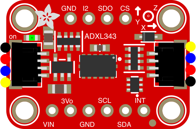
The Adafruit ADXL343 STEMMA QT (Part ID: 4097) is a compact, low-power 3-axis accelerometer designed for motion sensing and orientation detection. It features an I2C interface for easy integration into microcontroller-based projects and is equipped with the STEMMA QT connector system, enabling plug-and-play functionality. This accelerometer is ideal for applications such as tilt sensing, vibration monitoring, and gesture recognition in robotics, wearables, and IoT devices.
Explore Projects Built with Adafruit ADXL343 STEMMA QT
 Open Project in Cirkit Designer
 Open Project in Cirkit Designer
 Open Project in Cirkit Designer
 Open Project in Cirkit Designer
Explore Projects Built with Adafruit ADXL343 STEMMA QT
Open Project in Cirkit DesignerOpen Project in Cirkit DesignerOpen Project in Cirkit DesignerOpen Project in Cirkit DesignerTechnical Specifications
The ADXL343 accelerometer offers a wide range of features and capabilities, making it suitable for various applications. Below are the key technical details:
Key Specifications
| Parameter | Value |
|---|---|
| Operating Voltage | 3.3V to 5V |
| Communication Interface | I2C (default) or SPI |
| Measurement Range | ±2g, ±4g, ±8g, ±16g (configurable) |
| Sensitivity | 256 LSB/g (±2g range) |
| Data Rate | 0.1 Hz to 3200 Hz |
| Operating Temperature | -40°C to +85°C |
| Power Consumption | 40 µA (measurement mode), 0.1 µA (standby) |
| Dimensions | 25.5mm x 17.8mm x 4.6mm |
Pin Configuration
The ADXL343 STEMMA QT board has the following pinout:
| Pin Name | Description |
|---|---|
| VIN | Power input (3.3V to 5V) |
| GND | Ground |
| SCL | I2C clock line |
| SDA | I2C data line |
| STEMMA QT | Plug-and-play I2C connectors |
Usage Instructions
The Adafruit ADXL343 STEMMA QT is straightforward to use in a circuit. Below are the steps and best practices for integrating it into your project:
Connecting the ADXL343 to an Arduino UNO
Wiring: Use the STEMMA QT connectors for a quick and reliable connection. Alternatively, you can use jumper wires:
- Connect
VINto the Arduino's5Vpin. - Connect
GNDto the Arduino'sGNDpin. - Connect
SCLto the Arduino'sA5pin (I2C clock line). - Connect
SDAto the Arduino'sA4pin (I2C data line).
- Connect
Install Libraries: Download and install the Adafruit ADXL343 library and the Adafruit Unified Sensor library from the Arduino Library Manager.
Upload Example Code: Use the following example code to read acceleration data:
#include <Wire.h>
#include <Adafruit_Sensor.h>
#include <Adafruit_ADXL343.h>

// Create an ADXL343 object
Adafruit_ADXL343 accel = Adafruit_ADXL343(12345); // Pass an arbitrary sensor ID

void setup() {
  Serial.begin(9600);
  while (!Serial) {
    delay(10); // Wait for Serial Monitor to open
  }

  Serial.println("Adafruit ADXL343 Test");

  // Initialize the sensor
  if (!accel.begin()) {
    Serial.println("Failed to find ADXL343 chip");
    while (1) {
      delay(10); // Halt if sensor is not found
    }
  }
  Serial.println("ADXL343 Found!");

  // Set range to ±2g
  accel.setRange(ADXL343_RANGE_2_G);
  Serial.print("Range set to: ");
  Serial.println(accel.getRange());
}

void loop() {
  // Read acceleration data
  sensors_event_t event;
  accel.getEvent(&event);

  // Print acceleration values
  Serial.print("X: ");
  Serial.print(event.acceleration.x);
  Serial.print(" m/s^2, Y: ");
  Serial.print(event.acceleration.y);
  Serial.print(" m/s^2, Z: ");
  Serial.print(event.acceleration.z);
  Serial.println(" m/s^2");

  delay(500); // Delay for readability
}
Important Considerations
- Power Supply: Ensure the board is powered within the specified voltage range (3.3V to 5V).
- I2C Address: The default I2C address is
0x53. If you have multiple devices on the same I2C bus, ensure there are no address conflicts. - Mounting Orientation: The sensor's orientation affects the acceleration readings. Mount it securely to avoid vibrations or misalignment.
Troubleshooting and FAQs
Common Issues
Sensor Not Detected:
- Ensure the wiring is correct and secure.
- Verify that the I2C address matches the default (
0x53) or the configured address. - Check if the Adafruit ADXL343 library is installed correctly.
Incorrect or No Data:
- Confirm that the sensor is powered within the specified voltage range.
- Ensure the sensor is not exposed to excessive vibrations or shocks.
Arduino Code Compilation Errors:
- Verify that all required libraries are installed.
- Ensure the library versions are compatible with your Arduino IDE.
FAQs
Q: Can I use the ADXL343 with a 3.3V microcontroller?
A: Yes, the ADXL343 supports both 3.3V and 5V logic levels, making it compatible with a wide range of microcontrollers.
Q: How do I change the measurement range?
A: Use the setRange() function in the Adafruit ADXL343 library. For example, accel.setRange(ADXL343_RANGE_4_G); sets the range to ±4g.
Q: Can I use SPI instead of I2C?
A: Yes, the ADXL343 supports SPI communication. However, the STEMMA QT connectors are designed for I2C. For SPI, you will need to manually wire the SPI pins.
Q: What is the maximum cable length for the STEMMA QT connectors?
A: The maximum cable length depends on the I2C bus speed and environment. For standard I2C speeds (100 kHz), a cable length of up to 1 meter is generally reliable.
By following this documentation, you can effectively integrate the Adafruit ADXL343 STEMMA QT into your projects for accurate motion sensing and orientation detection.