Cirkit Designer Logo
Cirkit Designer
Your all-in-one circuit design IDE
Home / 
Component Documentation

How to Use nRF24L01: Examples, Pinouts, and Specs

Image of nRF24L01
Cirkit Designer LogoDesign with nRF24L01 in Cirkit Designer

Introduction

The nRF24L01 is a highly integrated, ultra-low power 2.4GHz transceiver module designed for wireless communication in a multitude of applications. It is widely used in the field of Internet of Things (IoT), remote control systems, and sensor networks due to its small form factor, low power consumption, and reliable data transmission capabilities.

Explore Projects Built with nRF24L01

Use Cirkit Designer to design, explore, and prototype these projects online. Some projects support real-time simulation. Click "Open Project" to start designing instantly!
Arduino 101 with NRF24L01 Wireless Communication Module
Image of RC Transmitter: A project utilizing nRF24L01 in a practical application
This circuit connects an Arduino 101 microcontroller to an NRF24L01 wireless transceiver module. The Arduino provides power, ground, and SPI communication lines to the NRF24L01, enabling wireless data transmission capabilities. The connections suggest that the Arduino can control the NRF24L01 to send and receive data wirelessly, likely for remote sensing or control applications.
Cirkit Designer LogoOpen Project in Cirkit Designer
Arduino Nano Wireless Communication System with nRF24L01 Module
Image of drone reciever: A project utilizing nRF24L01 in a practical application
This circuit connects an nRF24L01 wireless transceiver module to an Arduino Nano microcontroller through an adapter board. The Arduino Nano is configured to communicate with the nRF24L01 via SPI (Serial Peripheral Interface), using pins D9 and D10 for chip enable (CE) and chip select (CSN), and pins D11 to D13 for the SPI bus (MOSI, MISO, SCK). An electrolytic capacitor is connected across the power supply lines likely for power stabilization.
Cirkit Designer LogoOpen Project in Cirkit Designer
Arduino Nano and NRF24L01 Based Wireless Remote Control
Image of P.T.S CAR , REMOTE , ADVANCE , FINAL V1: A project utilizing nRF24L01 in a practical application
This circuit features an Arduino Nano microcontroller interfaced with an NRF24L01 wireless transceiver module, powered by a 4 x AAA battery mount. Four pushbuttons are connected to the Arduino's digital inputs with pull-up resistors, and they are used to send different wireless commands via the NRF24L01 module when pressed. The Arduino's SPI interface (D11/MOSI, D12/MISO, D13/SCK) is used for communication with the NRF24L01, and digital pins D9 and D10 are used for the module's CE and CSN pins, respectively.
Cirkit Designer LogoOpen Project in Cirkit Designer
Arduino Micro-Controlled Wireless Communication System with LCD Interface
Image of Festus project transmitter: A project utilizing nRF24L01 in a practical application
This circuit features an Arduino Micro microcontroller interfaced with an NRF24L01 wireless transceiver module, a 16x2 LCD screen with I2C communication, and a pushbutton. The Arduino Micro controls the NRF24L01 for wireless data communication and displays information on the LCD screen, while the pushbutton provides user input. A 7805 voltage regulator is used to step down the 12V power supply to 5V, powering the Arduino, the LCD, and the NRF24L01 module.
Cirkit Designer LogoOpen Project in Cirkit Designer

Explore Projects Built with nRF24L01

Use Cirkit Designer to design, explore, and prototype these projects online. Some projects support real-time simulation. Click "Open Project" to start designing instantly!
Image of RC Transmitter: A project utilizing nRF24L01 in a practical application
Arduino 101 with NRF24L01 Wireless Communication Module
This circuit connects an Arduino 101 microcontroller to an NRF24L01 wireless transceiver module. The Arduino provides power, ground, and SPI communication lines to the NRF24L01, enabling wireless data transmission capabilities. The connections suggest that the Arduino can control the NRF24L01 to send and receive data wirelessly, likely for remote sensing or control applications.
Cirkit Designer LogoOpen Project in Cirkit Designer
Image of drone reciever: A project utilizing nRF24L01 in a practical application
Arduino Nano Wireless Communication System with nRF24L01 Module
This circuit connects an nRF24L01 wireless transceiver module to an Arduino Nano microcontroller through an adapter board. The Arduino Nano is configured to communicate with the nRF24L01 via SPI (Serial Peripheral Interface), using pins D9 and D10 for chip enable (CE) and chip select (CSN), and pins D11 to D13 for the SPI bus (MOSI, MISO, SCK). An electrolytic capacitor is connected across the power supply lines likely for power stabilization.
Cirkit Designer LogoOpen Project in Cirkit Designer
Image of P.T.S CAR , REMOTE , ADVANCE , FINAL V1: A project utilizing nRF24L01 in a practical application
Arduino Nano and NRF24L01 Based Wireless Remote Control
This circuit features an Arduino Nano microcontroller interfaced with an NRF24L01 wireless transceiver module, powered by a 4 x AAA battery mount. Four pushbuttons are connected to the Arduino's digital inputs with pull-up resistors, and they are used to send different wireless commands via the NRF24L01 module when pressed. The Arduino's SPI interface (D11/MOSI, D12/MISO, D13/SCK) is used for communication with the NRF24L01, and digital pins D9 and D10 are used for the module's CE and CSN pins, respectively.
Cirkit Designer LogoOpen Project in Cirkit Designer
Image of Festus project transmitter: A project utilizing nRF24L01 in a practical application
Arduino Micro-Controlled Wireless Communication System with LCD Interface
This circuit features an Arduino Micro microcontroller interfaced with an NRF24L01 wireless transceiver module, a 16x2 LCD screen with I2C communication, and a pushbutton. The Arduino Micro controls the NRF24L01 for wireless data communication and displays information on the LCD screen, while the pushbutton provides user input. A 7805 voltage regulator is used to step down the 12V power supply to 5V, powering the Arduino, the LCD, and the NRF24L01 module.
Cirkit Designer LogoOpen Project in Cirkit Designer

Common Applications and Use Cases

  • Wireless keyboard and mouse
  • Remote controlled toys
  • Home automation systems
  • Wireless sensor networks
  • IoT devices
  • Drone communication systems

Technical Specifications

Key Technical Details

  • Frequency: 2.4GHz ISM band
  • Modulation: GFSK (Gaussian Frequency Shift Keying)
  • Data Rate: 250kbps, 1Mbps, or 2Mbps
  • Power Supply: 1.9 to 3.6V
  • Output Power: -18 to 0 dBm
  • Sensitivity: -82 dBm at 2Mbps
  • Current Consumption: 12.3mA at 0dBm output power
  • Operating Temperature: -40°C to 85°C

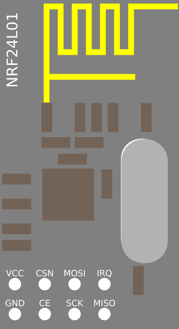
Pin Configuration and Descriptions

Pin Number Name Description
1 GND Ground
2 VCC Power supply (1.9 to 3.6V)
3 CE Chip Enable (activates RX or TX mode)
4 CSN Chip Select Not (SPI chip select)
5 SCK Serial Clock (SPI clock)
6 MOSI Master Out Slave In (SPI data to nRF24L01)
7 MISO Master In Slave Out (SPI data from nRF24L01)
8 IRQ Interrupt Request (active low)

Usage Instructions

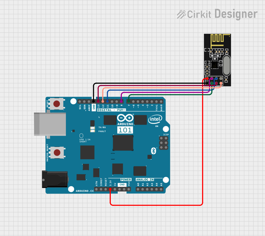
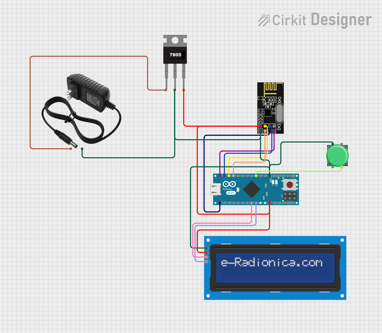
How to Use the Component in a Circuit

  1. Connect the VCC and GND pins to a stable 3.3V power supply.
  2. Interface the SPI pins (SCK, MOSI, MISO) with your microcontroller's corresponding SPI pins.
  3. Connect the CE pin to a digital I/O pin on your microcontroller to control the mode of the nRF24L01.
  4. Connect the CSN pin to another digital I/O pin for SPI communication enable.
  5. Optionally, connect the IRQ pin to an interrupt-capable pin on your microcontroller for interrupt-driven operation.

Important Considerations and Best Practices

  • Ensure that the power supply is clean and within the specified voltage range to avoid damaging the module.
  • Use bypass capacitors close to the power pins to filter out noise.
  • Keep the antenna area of the module clear from metal components to ensure proper signal transmission and reception.
  • When designing the PCB, provide a ground plane under the module to improve performance.
  • For reliable communication, ensure that both the transmitting and receiving modules are configured with the same channel and data rate.

Troubleshooting and FAQs

Common Issues Users Might Face

  • Data not being received: Ensure that both modules are powered correctly, configured with the same settings, and within range of each other.
  • Low range or poor signal quality: Check for obstructions or interference in the environment. Adjust the antenna position or consider using an external antenna if necessary.
  • Intermittent connectivity: Verify the integrity of the SPI connections and ensure that the power supply is stable.

Solutions and Tips for Troubleshooting

  • Double-check wiring, especially the SPI connections and power supply.
  • Use the IRQ pin to diagnose issues with the help of interrupt-driven status reporting.
  • Experiment with different channels to avoid interference from other 2.4GHz devices.
  • Ensure that the module is not in power-down or standby mode when attempting to communicate.

FAQs

Q: Can the nRF24L01 be used with an Arduino UNO? A: Yes, the nRF24L01 can be easily interfaced with an Arduino UNO using the SPI pins.

Q: What is the maximum range of the nRF24L01? A: The range can vary from 10 to 100 meters depending on the environment, antenna type, and power level settings.

Q: How many channels does the nRF24L01 support? A: The nRF24L01 supports 125 channels, which allows for multiple devices to communicate without interference.

Q: Can the nRF24L01 transmit and receive at the same time? A: No, the nRF24L01 cannot transmit and receive simultaneously as it is a half-duplex device.

Example Arduino Code

Below is an example of how to use the nRF24L01 with an Arduino UNO. This code initializes the module and sends a simple message.

#include <SPI.h>
#include "RF24.h"

// Create an instance of the RF24 library
RF24 radio(9, 10); // CE, CSN pins

void setup() {
  Serial.begin(9600);
  radio.begin(); // Initialize the nRF24L01 module
  radio.setPALevel(RF24_PA_LOW); // Set the power level
  radio.setChannel(76); // Set the channel
  radio.openWritingPipe(0xF0F0F0F0E1LL); // Open a writing pipe
  radio.stopListening(); // Enter transmit mode
}

void loop() {
  const char text[] = "Hello World";
  radio.write(&text, sizeof(text)); // Send the message
  delay(1000);
}

Remember to include the RF24 library in your Arduino IDE before compiling the code. This example assumes that the nRF24L01 module is connected correctly to the Arduino UNO. The RF24 library provides a simple interface for handling the nRF24L01's operations.