How to Use PPK2: Examples, Pinouts, and Specs
Introduction
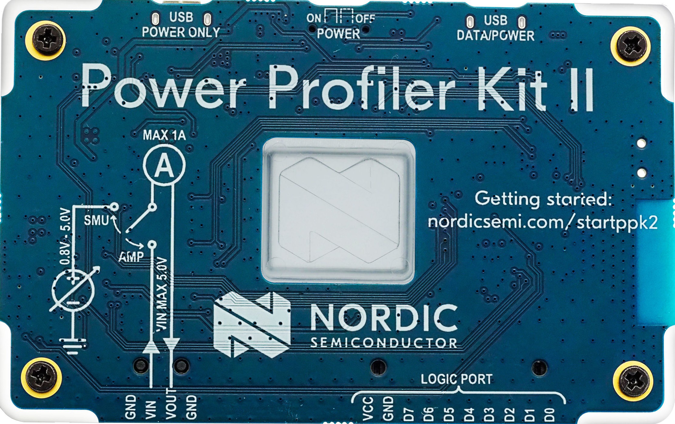
The PPK2 (Power Profiler Kit 2) is a versatile programmable power supply module developed by Nordic Semiconductor. It is designed for testing and powering electronic circuits with precision. The PPK2 allows users to measure current consumption, profile power usage, and supply power to devices under test (DUT). With its adjustable voltage and current settings, the PPK2 is an essential tool for developers working on low-power applications, such as IoT devices, wearables, and battery-powered systems.
Explore Projects Built with PPK2
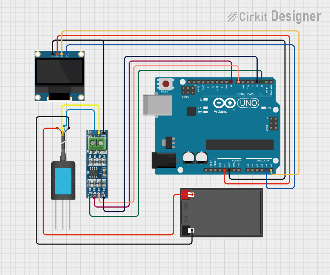

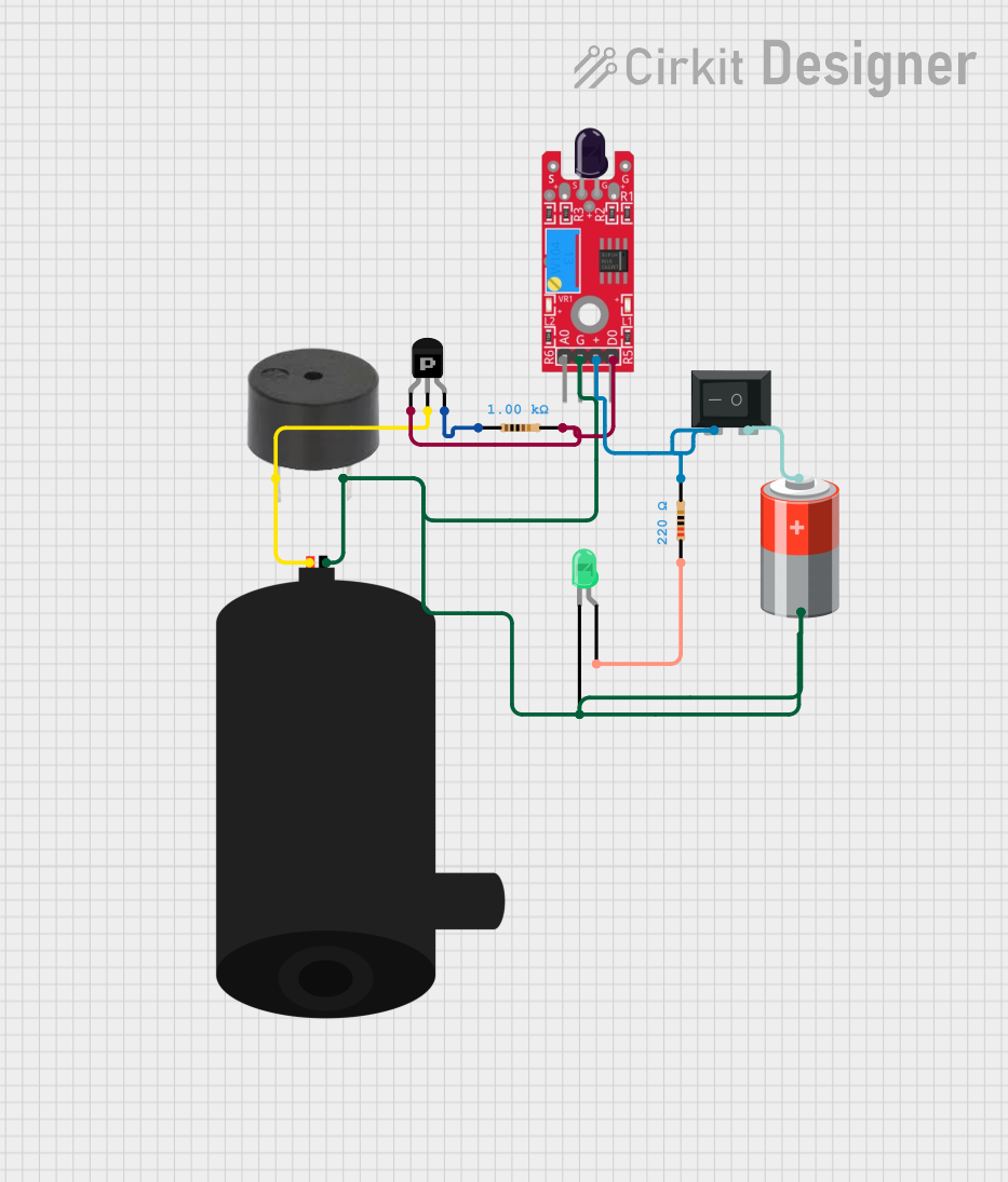

Explore Projects Built with PPK2
Common Applications and Use Cases
- Measuring current consumption of microcontrollers, sensors, and other components.
- Profiling power usage in low-power devices.
- Supplying power to circuits during development and testing.
- Debugging power-related issues in embedded systems.
- Evaluating energy efficiency in IoT and battery-operated devices.
Technical Specifications
The PPK2 offers a range of features and specifications to meet the needs of developers and engineers:
Key Technical Details
- Input Voltage: 4.0–5.5 V (via USB-C)
- Output Voltage Range: 0.8–5.0 V (programmable)
- Current Measurement Range: 100 nA to 1 A
- Measurement Resolution:
- 100 nA range: 100 nA resolution
- 1 µA range: 1 µA resolution
- 1 mA range: 1 µA resolution
- 10 mA range: 10 µA resolution
- Sampling Rate: Up to 100 kHz
- Interface: USB-C for power and data communication
- Supported Software: nRF Connect for Desktop (Power Profiler App)
Pin Configuration and Descriptions
The PPK2 features several connectors and pins for interfacing with the DUT. Below is a table describing the key pins and connectors:
| Pin/Connector | Description |
|---|---|
| VOUT+ | Positive output voltage pin for powering the DUT. |
| VOUT- | Ground pin for the DUT. |
| GND | Additional ground pin for connecting to the DUT. |
| MEAS+ | Positive pin for current measurement. |
| MEAS- | Negative pin for current measurement. |
| USB-C | USB-C connector for power input and communication with the host computer. |
Usage Instructions
The PPK2 is easy to set up and use for power profiling and supplying power to circuits. Follow the steps below to get started:
How to Use the PPK2 in a Circuit
- Connect the PPK2 to Your Computer:
- Use a USB-C cable to connect the PPK2 to your computer. Ensure the computer has the nRF Connect for Desktop software installed.
- Install the Power Profiler App:
- Open nRF Connect for Desktop and install the Power Profiler App.
- Connect the DUT:
- Connect the VOUT+ and VOUT- pins to the power input of your DUT.
- If you want to measure current, connect the MEAS+ and MEAS- pins in series with the DUT.
- Configure Voltage and Current Settings:
- Open the Power Profiler App and set the desired output voltage and current limits.
- Start Profiling:
- Use the app to monitor current consumption, voltage, and power usage in real time.
Important Considerations and Best Practices
- Avoid Overloading: Ensure the DUT does not draw more current than the PPK2's maximum limit of 1 A.
- Use Proper Connections: Double-check all connections to avoid short circuits or incorrect measurements.
- Calibrate for Accuracy: For precise measurements, ensure the PPK2 is properly calibrated using the Power Profiler App.
- Use Shielded Cables: To minimize noise and interference, use shielded cables for connections.
Example: Using PPK2 with an Arduino UNO
The PPK2 can be used to measure the power consumption of an Arduino UNO. Below is an example setup:
- Connect the VOUT+ pin of the PPK2 to the 5V pin of the Arduino UNO.
- Connect the VOUT- pin of the PPK2 to the GND pin of the Arduino UNO.
- Open the Power Profiler App and set the output voltage to 5.0 V.
- Monitor the current consumption of the Arduino UNO in real time.
Example Code for Arduino UNO
Here is a simple Arduino sketch to toggle an LED and observe the power consumption using the PPK2:
// Simple LED Blink Example for Power Profiling
// This code toggles an LED on pin 13 to observe power consumption.

const int ledPin = 13; // Pin connected to the onboard LED

void setup() {
  pinMode(ledPin, OUTPUT); // Set the LED pin as an output
}

void loop() {
  digitalWrite(ledPin, HIGH); // Turn the LED on
  delay(1000);                // Wait for 1 second
  digitalWrite(ledPin, LOW);  // Turn the LED off
  delay(1000);                // Wait for 1 second
}
Troubleshooting and FAQs
Common Issues and Solutions
PPK2 Not Detected by the Computer:
- Ensure the USB-C cable is properly connected.
- Verify that the nRF Connect for Desktop software is installed and up to date.
- Try using a different USB port or cable.
Incorrect Current Measurements:
- Check that the MEAS+ and MEAS- pins are correctly connected in series with the DUT.
- Ensure the DUT's current draw is within the PPK2's measurement range.
Voltage Output Not Stable:
- Verify that the output voltage is correctly configured in the Power Profiler App.
- Check for loose connections or short circuits in the DUT.
Overcurrent Protection Triggered:
- Reduce the current draw of the DUT to stay within the PPK2's 1 A limit.
- Check for any faults or excessive loads in the DUT.
FAQs
Q: Can the PPK2 measure current below 1 µA?
A: Yes, the PPK2 can measure currents as low as 100 nA with a resolution of 100 nA.
Q: Is the PPK2 compatible with macOS and Linux?
A: Yes, the nRF Connect for Desktop software, including the Power Profiler App, is available for Windows, macOS, and Linux.
Q: Can I use the PPK2 to power a 3.3 V device?
A: Yes, the PPK2 supports output voltages from 0.8 V to 5.0 V, making it suitable for 3.3 V devices.
Q: How do I update the firmware on the PPK2?
A: Firmware updates can be performed through the nRF Connect for Desktop software when prompted.
By following this documentation, users can effectively utilize the PPK2 for power profiling and testing electronic circuits.