Cirkit Designer Logo
Cirkit Designer
Your all-in-one circuit design IDE
Home / 
Component Documentation

How to Use Pulse Oximeter: Examples, Pinouts, and Specs

Image of Pulse Oximeter
Cirkit Designer LogoDesign with Pulse Oximeter in Cirkit Designer

Introduction

The Pulse Oximeter is a medical device designed to non-invasively measure the oxygen saturation level (SpO2) in a person's blood. It operates by emitting light through a translucent part of the body, such as a fingertip or earlobe, and analyzing the light absorption to determine oxygen levels. This device is widely used in healthcare settings, fitness monitoring, and personal health tracking.

Explore Projects Built with Pulse Oximeter

Use Cirkit Designer to design, explore, and prototype these projects online. Some projects support real-time simulation. Click "Open Project" to start designing instantly!
ESP32-Based Heart Rate and SpO2 Monitor with OLED Display and Wi-Fi Connectivity
Image of hartbit diagram: A project utilizing Pulse Oximeter in a practical application
This circuit is a wearable health monitoring device that uses an ESP32 microcontroller to read data from a MAX30102 pulse oximeter sensor and display it on a 0.96" OLED screen. The device is powered by a Li-ion 18650 battery, which is managed by a TP4056 charging module, and it transmits data to a remote server using Blynk over WiFi.
Cirkit Designer LogoOpen Project in Cirkit Designer
ESP8266 NodeMCU with OLED Display and MAX30100 Pulse Oximeter
Image of Monitor: A project utilizing Pulse Oximeter in a practical application
This circuit features an ESP8266 NodeMCU microcontroller connected to a 0.96" OLED display and a MAX30100 pulse oximeter sensor. The OLED display and MAX30100 sensor are interfaced with the ESP8266 via I2C communication, as indicated by the shared SDA and SCK lines. The circuit is likely designed to measure and display heart rate and blood oxygen saturation levels, with the ESP8266 processing the sensor data and managing the display output.
Cirkit Designer LogoOpen Project in Cirkit Designer
Arduino Nano-Based Pulse Oximeter with OLED Display
Image of Pulse Oximeter- Anurag Deb: A project utilizing Pulse Oximeter in a practical application
This circuit is designed around an Arduino Nano microcontroller, which interfaces with a 0.96" OLED display and a MAX30102 heart rate and oxygen sensor. The OLED display shows the user's heart rate and blood oxygen saturation, while the MAX30102 sensor measures these biometrics. A pushbutton is included to allow user interaction, likely for navigating the display or setting the device into a sleep mode.
Cirkit Designer LogoOpen Project in Cirkit Designer
Battery-Powered Heart Rate and SpO2 Monitor with OLED Display using MAX30102 and Arduino Nano
Image of smart watch: A project utilizing Pulse Oximeter in a practical application
This circuit is a portable health monitoring device that uses an Arduino Nano to interface with a MAX30102 heart rate and SpO2 sensor and a 0.96" OLED display via I2C. The device is powered by a 3.7V LiPo battery, which is managed by a TP4056 charging module and a boost converter to provide a stable 5V supply.
Cirkit Designer LogoOpen Project in Cirkit Designer

Explore Projects Built with Pulse Oximeter

Use Cirkit Designer to design, explore, and prototype these projects online. Some projects support real-time simulation. Click "Open Project" to start designing instantly!
Image of hartbit diagram: A project utilizing Pulse Oximeter in a practical application
ESP32-Based Heart Rate and SpO2 Monitor with OLED Display and Wi-Fi Connectivity
This circuit is a wearable health monitoring device that uses an ESP32 microcontroller to read data from a MAX30102 pulse oximeter sensor and display it on a 0.96" OLED screen. The device is powered by a Li-ion 18650 battery, which is managed by a TP4056 charging module, and it transmits data to a remote server using Blynk over WiFi.
Cirkit Designer LogoOpen Project in Cirkit Designer
Image of Monitor: A project utilizing Pulse Oximeter in a practical application
ESP8266 NodeMCU with OLED Display and MAX30100 Pulse Oximeter
This circuit features an ESP8266 NodeMCU microcontroller connected to a 0.96" OLED display and a MAX30100 pulse oximeter sensor. The OLED display and MAX30100 sensor are interfaced with the ESP8266 via I2C communication, as indicated by the shared SDA and SCK lines. The circuit is likely designed to measure and display heart rate and blood oxygen saturation levels, with the ESP8266 processing the sensor data and managing the display output.
Cirkit Designer LogoOpen Project in Cirkit Designer
Image of Pulse Oximeter- Anurag Deb: A project utilizing Pulse Oximeter in a practical application
Arduino Nano-Based Pulse Oximeter with OLED Display
This circuit is designed around an Arduino Nano microcontroller, which interfaces with a 0.96" OLED display and a MAX30102 heart rate and oxygen sensor. The OLED display shows the user's heart rate and blood oxygen saturation, while the MAX30102 sensor measures these biometrics. A pushbutton is included to allow user interaction, likely for navigating the display or setting the device into a sleep mode.
Cirkit Designer LogoOpen Project in Cirkit Designer
Image of smart watch: A project utilizing Pulse Oximeter in a practical application
Battery-Powered Heart Rate and SpO2 Monitor with OLED Display using MAX30102 and Arduino Nano
This circuit is a portable health monitoring device that uses an Arduino Nano to interface with a MAX30102 heart rate and SpO2 sensor and a 0.96" OLED display via I2C. The device is powered by a 3.7V LiPo battery, which is managed by a TP4056 charging module and a boost converter to provide a stable 5V supply.
Cirkit Designer LogoOpen Project in Cirkit Designer

Common Applications and Use Cases

  • Monitoring oxygen saturation levels in patients with respiratory or cardiac conditions.
  • Fitness tracking during exercise or high-altitude activities.
  • Sleep studies to detect conditions like sleep apnea.
  • Continuous health monitoring in wearable devices.

Technical Specifications

The following table outlines the key technical details of a typical Pulse Oximeter module:

Parameter Value
Operating Voltage 3.3V to 5V
Operating Current 20mA to 50mA
Measurement Range (SpO2) 70% to 100%
Measurement Range (Pulse) 30 bpm to 250 bpm
Accuracy (SpO2) ±2% (80% to 100% range)
Accuracy (Pulse) ±3 bpm
Communication Interface I2C or UART
Sensor Type Red and Infrared LED with Photodiode

Pin Configuration and Descriptions

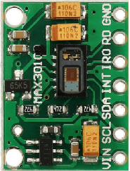
Below is the pinout for a common Pulse Oximeter module (e.g., MAX30100 or MAX30102):

Pin Name Description
1 VCC Power supply input (3.3V to 5V).
2 GND Ground connection.
3 SDA I2C data line for communication with microcontroller.
4 SCL I2C clock line for communication with microcontroller.
5 INT Interrupt pin for data-ready signal (optional).

Usage Instructions

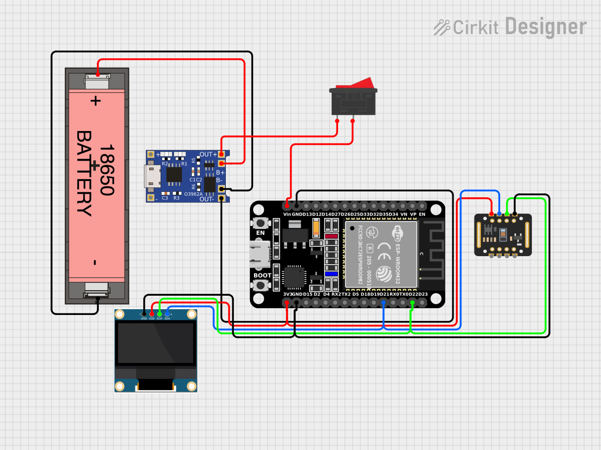
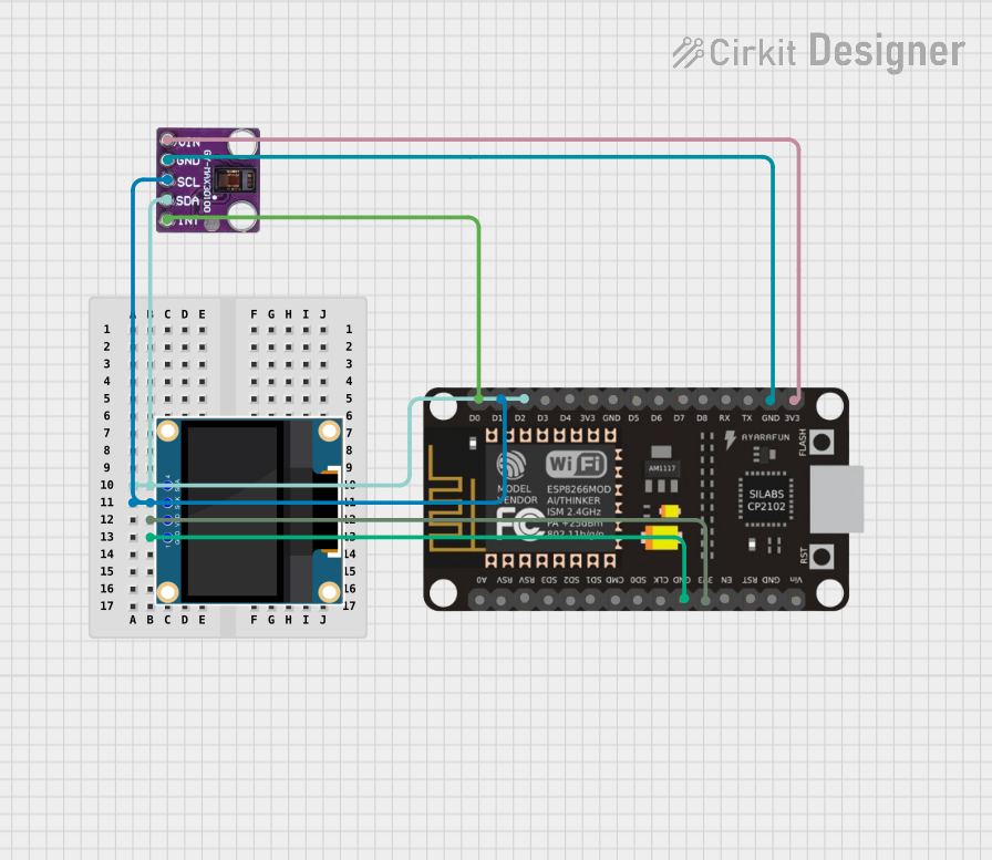
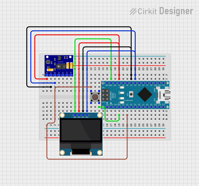
How to Use the Component in a Circuit

  1. Power the Module: Connect the VCC pin to a 3.3V or 5V power source and the GND pin to ground.
  2. Connect Communication Lines: Use the SDA and SCL pins to interface with a microcontroller (e.g., Arduino UNO) via the I2C protocol.
  3. Place the Sensor: Position the sensor on a fingertip or earlobe for accurate readings.
  4. Read Data: Use the microcontroller to read SpO2 and pulse rate data from the module.

Important Considerations and Best Practices

  • Ensure the sensor is securely placed on the measurement site to avoid motion artifacts.
  • Avoid direct exposure to ambient light, as it may interfere with readings.
  • Use pull-up resistors (typically 4.7kΩ) on the SDA and SCL lines for proper I2C communication.
  • Calibrate the sensor if required, following the manufacturer's guidelines.

Example Code for Arduino UNO

Below is an example of how to interface a MAX30102 Pulse Oximeter module with an Arduino UNO:

#include <Wire.h>
#include "MAX30105.h" // Include the library for MAX30102

MAX30105 pulseOximeter; // Create an instance of the sensor

void setup() {
  Serial.begin(9600); // Initialize serial communication
  Serial.println("Initializing Pulse Oximeter...");

  // Initialize the sensor
  if (!pulseOximeter.begin()) {
    Serial.println("Pulse Oximeter not detected. Check connections.");
    while (1); // Halt execution if the sensor is not found
  }

  Serial.println("Pulse Oximeter initialized successfully.");
}

void loop() {
  // Read SpO2 and pulse rate
  float spo2 = pulseOximeter.getSpO2(); // Get oxygen saturation level
  float heartRate = pulseOximeter.getHeartRate(); // Get pulse rate

  // Print the readings to the serial monitor
  Serial.print("SpO2: ");
  Serial.print(spo2);
  Serial.print("%, Heart Rate: ");
  Serial.print(heartRate);
  Serial.println(" bpm");

  delay(1000); // Wait for 1 second before the next reading
}

Notes:

  • Install the appropriate library for the MAX30102 (e.g., SparkFun MAX3010x library) in the Arduino IDE.
  • Ensure the I2C address of the module matches the library's default or modify it accordingly.

Troubleshooting and FAQs

Common Issues and Solutions

  1. No Data Output:

    • Verify the power connections (VCC and GND).
    • Check the I2C connections (SDA and SCL) and ensure pull-up resistors are used.
    • Confirm the I2C address of the module matches the code.
  2. Inaccurate Readings:

    • Ensure the sensor is properly positioned on the measurement site.
    • Minimize motion and ambient light interference during measurements.
    • Check for proper calibration of the sensor.
  3. Module Not Detected:

    • Ensure the correct library is installed and included in the code.
    • Verify the wiring and ensure the module is powered.

FAQs

Q: Can the Pulse Oximeter measure SpO2 below 70%?
A: Most Pulse Oximeters are designed to measure SpO2 levels between 70% and 100%. Readings below 70% may not be accurate.

Q: Can I use the Pulse Oximeter with a 3.3V microcontroller?
A: Yes, the module typically supports both 3.3V and 5V logic levels. Verify the datasheet for compatibility.

Q: How do I reduce noise in the readings?
A: Use a stable power supply, minimize motion during measurements, and shield the sensor from ambient light.

This documentation provides a comprehensive guide to understanding, using, and troubleshooting a Pulse Oximeter module.