How to Use QTR-8A: Examples, Pinouts, and Specs
Introduction
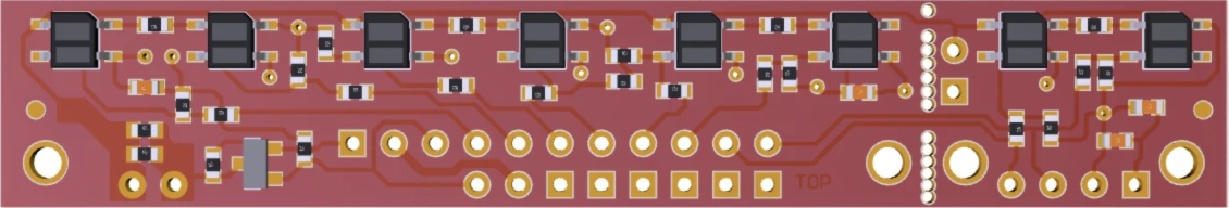
The QTR-8A is an array of eight infrared (IR) emitter and detector pairs designed for line sensing and object detection. Each pair consists of an IR LED and a phototransistor, enabling the detection of reflected IR light. The module outputs analog signals corresponding to the intensity of reflected light, making it ideal for applications requiring precise line following or object detection.
Explore Projects Built with QTR-8A
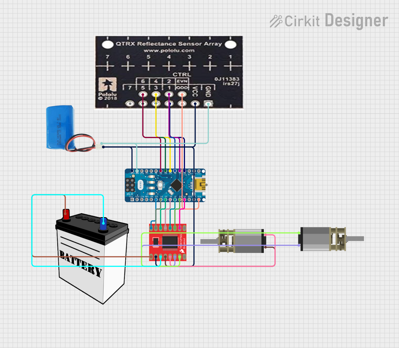

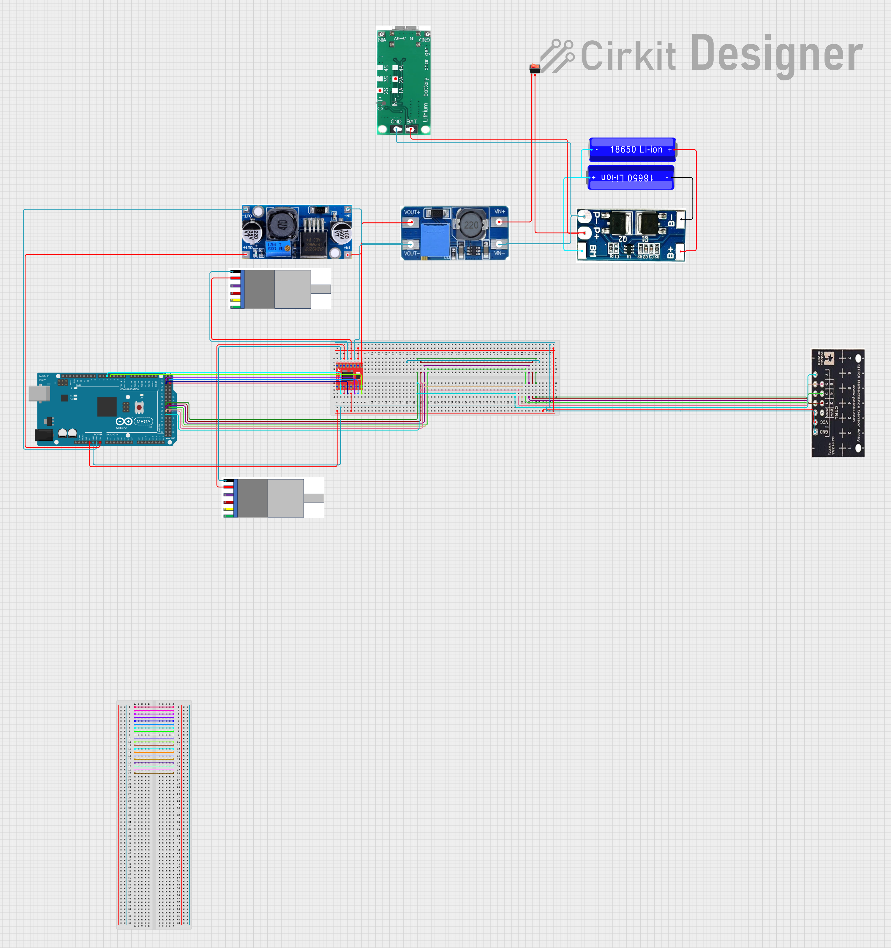
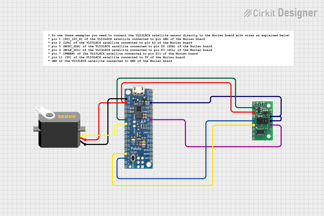
Explore Projects Built with QTR-8A
Common Applications
- Line-following robots
- Edge detection in robotics
- Object detection in automation systems
- Position tracking in conveyor systems
Technical Specifications
The QTR-8A is a versatile sensor array with the following key specifications:
| Parameter | Value |
|---|---|
| Operating Voltage | 5V DC |
| Operating Current | ~100 mA (all emitters on) |
| Output Type | Analog voltage (0V to ~3.3V) |
| Sensor Count | 8 IR emitter-detector pairs |
| Detection Range | 3 mm to 6 mm (optimal) |
| Dimensions | 76.2 mm x 12.7 mm x 3.2 mm |
| Weight | 3.09 g |
Pin Configuration
The QTR-8A has a 10-pin interface. The pinout is as follows:
| Pin | Name | Description |
|---|---|---|
| 1 | VCC | Power supply input (5V DC) |
| 2 | GND | Ground connection |
| 3 | OUT1 | Analog output for sensor 1 |
| 4 | OUT2 | Analog output for sensor 2 |
| 5 | OUT3 | Analog output for sensor 3 |
| 6 | OUT4 | Analog output for sensor 4 |
| 7 | OUT5 | Analog output for sensor 5 |
| 8 | OUT6 | Analog output for sensor 6 |
| 9 | OUT7 | Analog output for sensor 7 |
| 10 | OUT8 | Analog output for sensor 8 |
Usage Instructions
How to Use the QTR-8A in a Circuit
- Power the Module: Connect the
VCCpin to a 5V DC power source and theGNDpin to ground. - Connect Outputs: Each sensor's analog output (OUT1 to OUT8) can be connected to an analog input pin of a microcontroller (e.g., Arduino).
- Read Sensor Data: The analog output voltage corresponds to the intensity of reflected IR light. A higher voltage indicates more reflection (e.g., a white surface), while a lower voltage indicates less reflection (e.g., a black surface).
Important Considerations
- Optimal Distance: The QTR-8A works best at a distance of 3 mm to 6 mm from the surface being detected.
- Ambient Light: Minimize ambient IR light interference by shielding the sensor or using it in controlled lighting conditions.
- Calibration: Calibrate the sensor for your specific application to account for variations in surface reflectivity.
Example: Using QTR-8A with Arduino UNO
Below is an example code snippet to read data from the QTR-8A using an Arduino UNO:
// QTR-8A Example Code for Arduino UNO
// This code reads analog values from the QTR-8A sensor array and prints them
// to the Serial Monitor. Ensure the QTR-8A is connected to the correct pins.

const int sensorPins[8] = {A0, A1, A2, A3, A4, A5, A6, A7}; // Analog pins
int sensorValues[8]; // Array to store sensor readings

void setup() {
  Serial.begin(9600); // Initialize serial communication at 9600 baud
  for (int i = 0; i < 8; i++) {
    pinMode(sensorPins[i], INPUT); // Set sensor pins as input
  }
}

void loop() {
  // Read values from each sensor
  for (int i = 0; i < 8; i++) {
    sensorValues[i] = analogRead(sensorPins[i]); // Read analog value
  }

  // Print sensor values to Serial Monitor
  for (int i = 0; i < 8; i++) {
    Serial.print("Sensor ");
    Serial.print(i + 1);
    Serial.print(": ");
    Serial.print(sensorValues[i]);
    Serial.print("\t"); // Tab space for better readability
  }
  Serial.println(); // New line after printing all sensor values
  delay(100); // Small delay for stability
}
Best Practices
- Use pull-up resistors if required for stable analog readings.
- Mount the sensor array securely to avoid vibrations that could affect readings.
- Regularly clean the sensor surface to remove dust or debris.
Troubleshooting and FAQs
Common Issues and Solutions
No Output or Incorrect Readings:
- Ensure the module is powered with 5V and properly grounded.
- Verify connections between the sensor outputs and the microcontroller's analog pins.
Inconsistent Readings:
- Check for ambient IR interference and reduce it if possible.
- Ensure the sensor is at the optimal distance (3 mm to 6 mm) from the surface.
All Sensors Show High or Low Values:
- Verify that the surface being detected has sufficient contrast (e.g., black line on a white background).
- Clean the sensor array to remove any dirt or smudges.
FAQs
Q: Can the QTR-8A detect colors?
A: No, the QTR-8A is designed to detect the intensity of reflected IR light, not specific colors.
Q: How do I calibrate the QTR-8A?
A: Calibration involves recording the minimum and maximum sensor readings for your specific surface and adjusting your code to map these values to a usable range.
Q: Can I use fewer than 8 sensors?
A: Yes, you can use only the sensors you need by connecting their outputs to your microcontroller and leaving the others unconnected.
Q: Is the QTR-8A compatible with 3.3V systems?
A: The QTR-8A requires a 5V power supply, but its analog outputs can be read by 3.3V systems as long as the microcontroller's analog input pins can tolerate 5V signals.
This concludes the documentation for the QTR-8A.