
How to Use MPU6050: Examples, Pinouts, and Specs
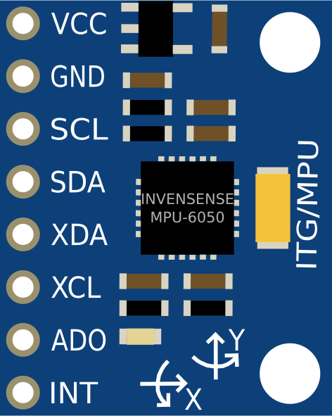
 Design with MPU6050 in Cirkit Designer
Introduction
The MPU6050 is a 6-axis motion tracking device that combines a 3-axis gyroscope and a 3-axis accelerometer on a single chip. This integration enables the measurement of angular velocity and acceleration in three-dimensional space, making it a versatile and widely used sensor in motion tracking applications. The MPU6050 also includes a Digital Motion Processor (DMP) for advanced motion processing and can communicate with microcontrollers via the I2C protocol.
Explore Projects Built with MPU6050
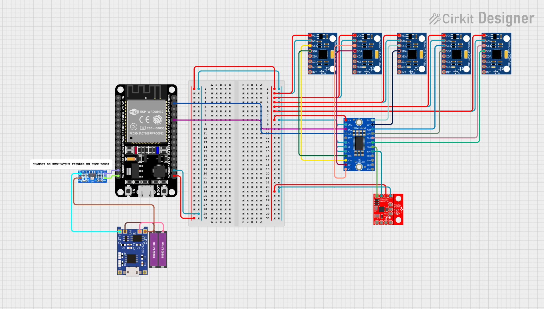 Open Project in Cirkit Designer
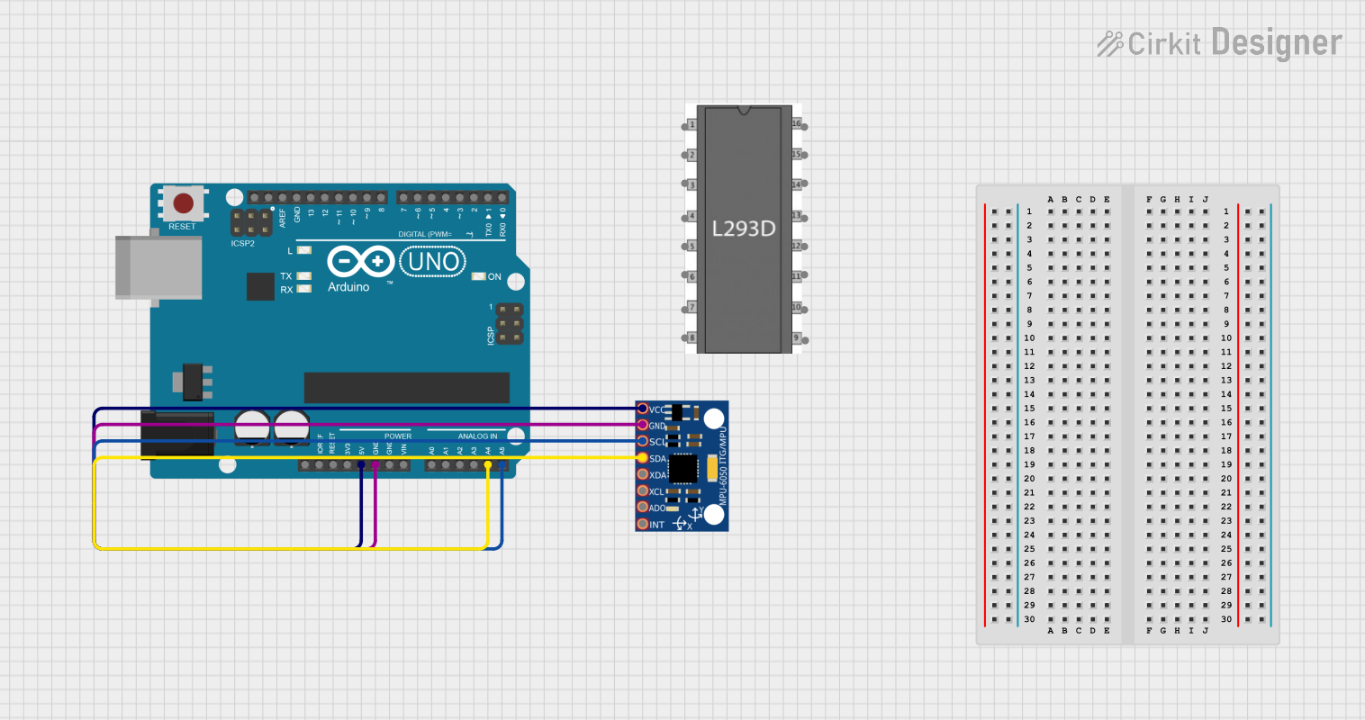 Open Project in Cirkit Designer
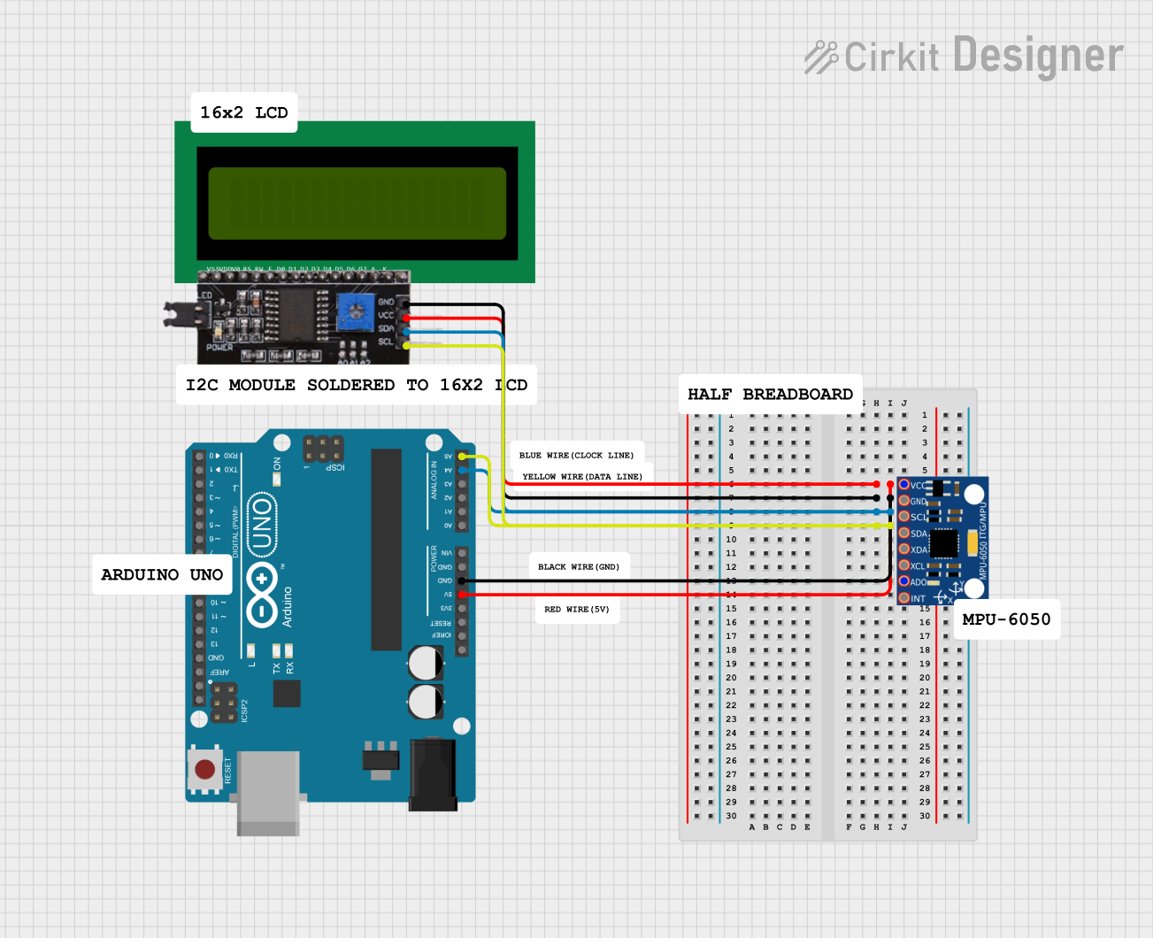 Open Project in Cirkit Designer
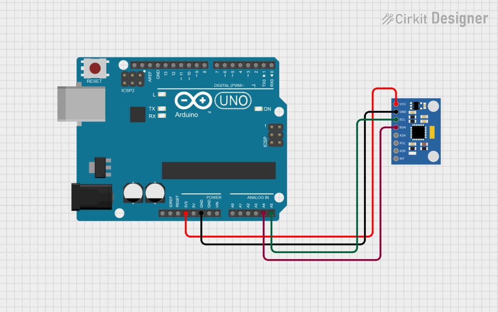 Open Project in Cirkit Designer
Explore Projects Built with MPU6050
Open Project in Cirkit DesignerOpen Project in Cirkit DesignerOpen Project in Cirkit DesignerOpen Project in Cirkit DesignerCommon Applications and Use Cases
- Robotics for motion tracking and stabilization
- Drones for flight control and orientation sensing
- Wearable devices for activity monitoring
- Gaming controllers for motion-based input
- Industrial equipment for vibration analysis
Technical Specifications
Key Technical Details
- Supply Voltage: 2.375V to 3.46V (typical 3.3V)
- Communication Protocol: I2C (up to 400kHz)
- Gyroscope Range: ±250, ±500, ±1000, ±2000 degrees/second
- Accelerometer Range: ±2g, ±4g, ±8g, ±16g
- Operating Temperature: -40°C to +85°C
- Power Consumption: 3.9mA (typical in active mode)
- Package: 24-pin QFN
Pin Configuration and Descriptions
The MPU6050 has 8 primary pins for interfacing. Below is the pinout description:
| Pin | Name | Description |
|---|---|---|
| 1 | VCC | Power supply input (2.375V to 3.46V). |
| 2 | GND | Ground connection. |
| 3 | SCL | I2C clock line. Connect to the microcontroller's SCL pin. |
| 4 | SDA | I2C data line. Connect to the microcontroller's SDA pin. |
| 5 | AD0 | I2C address select. Connect to GND for address 0x68 or VCC for 0x69. |
| 6 | INT | Interrupt output. Used for signaling data availability or motion detection. |
| 7 | FSYNC | Frame synchronization input. Typically left unconnected in most applications. |
| 8 | RESV | Reserved. Do not connect. |
Usage Instructions
How to Use the MPU6050 in a Circuit
- Power Supply: Connect the VCC pin to a 3.3V power source and the GND pin to ground.
- I2C Communication: Connect the SCL and SDA pins to the corresponding I2C pins on your microcontroller. Use pull-up resistors (typically 4.7kΩ) on the SCL and SDA lines if not already present.
- Address Selection: Set the AD0 pin to GND for the default I2C address
0x68or to VCC for0x69. - Interrupts (Optional): Connect the INT pin to a GPIO pin on your microcontroller if you want to use interrupt-based data reading.
Important Considerations and Best Practices
- Use decoupling capacitors (e.g., 0.1µF) near the VCC pin to stabilize the power supply.
- Ensure proper pull-up resistors are used on the I2C lines for reliable communication.
- Avoid excessive vibrations or shocks to the sensor, as they may affect accuracy.
- Calibrate the sensor for your specific application to improve measurement precision.
Example Code for Arduino UNO
Below is an example of how to interface the MPU6050 with an Arduino UNO using the I2C protocol:
#include <Wire.h>
#include <MPU6050.h>

// Create an MPU6050 object
MPU6050 mpu;

// Setup function
void setup() {
  Serial.begin(9600); // Initialize serial communication at 9600 baud
  Wire.begin();       // Initialize I2C communication

  // Initialize the MPU6050
  if (!mpu.begin(MPU6050_SCALE_2000DPS, MPU6050_RANGE_2G)) {
    Serial.println("Could not find a valid MPU6050 sensor, check connections!");
    while (1); // Halt execution if initialization fails
  }

  // Configure the sensor
  mpu.setThreshold(3); // Set motion detection threshold
  Serial.println("MPU6050 initialized successfully!");
}

// Loop function
void loop() {
  Vector rawAccel = mpu.readRawAccel(); // Read raw accelerometer data
  Vector rawGyro = mpu.readRawGyro();   // Read raw gyroscope data

  // Print accelerometer data
  Serial.print("Accel X: "); Serial.print(rawAccel.XAxis);
  Serial.print(" | Y: "); Serial.print(rawAccel.YAxis);
  Serial.print(" | Z: "); Serial.println(rawAccel.ZAxis);

  // Print gyroscope data
  Serial.print("Gyro X: "); Serial.print(rawGyro.XAxis);
  Serial.print(" | Y: "); Serial.print(rawGyro.YAxis);
  Serial.print(" | Z: "); Serial.println(rawGyro.ZAxis);

  delay(500); // Wait for 500ms before the next reading
}
Troubleshooting and FAQs
Common Issues and Solutions
No Data or Incorrect Readings:
- Ensure the I2C connections (SCL, SDA) are properly wired and have pull-up resistors.
- Verify the I2C address (default
0x68or0x69) matches the configuration in your code. - Check the power supply voltage (2.375V to 3.46V) and ensure it is stable.
Sensor Not Detected:
- Confirm that the AD0 pin is correctly set for the desired I2C address.
- Use an I2C scanner sketch to detect the sensor's address.
Inconsistent or Noisy Data:
- Perform sensor calibration to account for offsets and biases.
- Minimize external vibrations and electromagnetic interference.
Interrupt Pin Not Working:
- Ensure the INT pin is connected to a GPIO pin configured as an input.
- Verify that the interrupt functionality is enabled in the sensor's configuration.
FAQs
Q: Can the MPU6050 operate at 5V?
A: No, the MPU6050 operates at a maximum voltage of 3.46V. Use a voltage regulator or level shifter if interfacing with a 5V system.
Q: How do I calibrate the MPU6050?
A: Calibration involves measuring and compensating for offsets in the accelerometer and gyroscope readings. Libraries like MPU6050 or MPU6050_DMP often include calibration functions.
Q: Can I use the MPU6050 without the DMP?
A: Yes, you can directly read raw accelerometer and gyroscope data without using the DMP.
Q: What is the maximum sampling rate of the MPU6050?
A: The MPU6050 supports a maximum sampling rate of 1kHz for both accelerometer and gyroscope data.
By following this documentation, you can effectively integrate and utilize the MPU6050 in your projects.