
How to Use CPU Fan Connector Male 4 Pin: Examples, Pinouts, and Specs
 Design with CPU Fan Connector Male 4 Pin in Cirkit Designer
Introduction
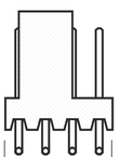
The CPU Fan Connector Male 4 Pin is a widely used electronic component designed to connect a CPU fan to a motherboard. This connector facilitates the delivery of power to the fan and enables speed control through PWM (Pulse Width Modulation). It is an essential component in modern computer systems, ensuring efficient cooling and thermal management.
Explore Projects Built with CPU Fan Connector Male 4 Pin
 Open Project in Cirkit Designer
 Open Project in Cirkit Designer
 Open Project in Cirkit Designer
 Open Project in Cirkit Designer
Explore Projects Built with CPU Fan Connector Male 4 Pin
Open Project in Cirkit DesignerOpen Project in Cirkit DesignerOpen Project in Cirkit DesignerOpen Project in Cirkit DesignerCommon Applications and Use Cases
- Connecting CPU fans to motherboards in desktop computers.
- Enabling fan speed control for optimized cooling and noise reduction.
- Used in custom PC builds and repairs.
- Suitable for other 4-pin fan applications requiring PWM control.
Technical Specifications
The following table outlines the key technical details of the CPU Fan Connector Male 4 Pin:
| Parameter | Specification |
|---|---|
| Manufacturer | Generic |
| Number of Pins | 4 |
| Pin Pitch | 2.54 mm |
| Voltage Rating | 12V DC (typical for CPU fans) |
| Current Rating | Up to 1A per pin |
| Material | Plastic housing with metal contacts |
| Compatibility | Standard 4-pin CPU fan headers |
Pin Configuration and Descriptions
The 4-pin male connector has the following pinout:
| Pin Number | Name | Description |
|---|---|---|
| 1 | GND | Ground connection for the fan. |
| 2 | +12V | Power supply for the fan (typically 12V DC). |
| 3 | Tachometer | Outputs a signal to measure the fan's speed (RPM). |
| 4 | PWM | Pulse Width Modulation signal for controlling the fan speed. |
Usage Instructions
How to Use the Component in a Circuit
- Identify the Pins: Ensure you correctly identify the pins on the connector (GND, +12V, Tachometer, PWM).
- Connect to Motherboard: Plug the male connector into the corresponding 4-pin CPU fan header on the motherboard.
- Secure the Connection: Ensure the connector is firmly seated to avoid loose connections.
- Fan Speed Control: Use the motherboard's BIOS or software to configure fan speed settings via PWM.
Important Considerations and Best Practices
- Pin Alignment: Double-check the pin alignment to avoid damaging the fan or motherboard.
- Voltage Compatibility: Ensure the fan operates at 12V DC, as this is the standard voltage for CPU fans.
- Avoid Overcurrent: Do not exceed the current rating of 1A per pin to prevent overheating or damage.
- PWM Signal: If using a custom circuit, ensure the PWM signal is within the fan's specifications (typically 25 kHz).
Example: Connecting to an Arduino UNO
The CPU Fan Connector Male 4 Pin can also be used with an Arduino UNO for custom fan control. Below is an example code snippet to control fan speed using PWM:
// Example: Controlling a 4-pin CPU fan with Arduino UNO
// Connect the fan's PWM pin to Arduino pin 9
// Ensure the fan's GND and +12V are connected to an external power source

const int pwmPin = 9; // Arduino pin connected to the fan's PWM pin
int fanSpeed = 128;   // Fan speed (0-255, where 255 is 100% duty cycle)

void setup() {
  pinMode(pwmPin, OUTPUT); // Set the PWM pin as an output
}

void loop() {
  analogWrite(pwmPin, fanSpeed); // Write PWM signal to control fan speed
  delay(1000);                  // Wait for 1 second
  fanSpeed = (fanSpeed + 64) % 256; // Increment fan speed (wraps around at 255)
}
Note: The fan's +12V and GND pins must be connected to an external 12V power source, as the Arduino cannot supply sufficient power for the fan.
Troubleshooting and FAQs
Common Issues Users Might Face
Fan Not Spinning:
- Cause: Incorrect pin connections or insufficient power supply.
- Solution: Verify the pin connections and ensure the fan is receiving 12V DC.
Fan Speed Not Adjustable:
- Cause: PWM signal not properly configured or incompatible fan.
- Solution: Check the PWM signal frequency and ensure it matches the fan's requirements.
Overheating Connector:
- Cause: Excessive current draw or poor contact.
- Solution: Ensure the fan's current draw does not exceed 1A and check for secure connections.
No Tachometer Signal:
- Cause: Faulty fan or disconnected tachometer pin.
- Solution: Test with a different fan and verify the tachometer pin connection.
Solutions and Tips for Troubleshooting
- Use a multimeter to check voltage and continuity on the connector pins.
- Refer to the motherboard manual for proper fan header configuration.
- If using an Arduino, ensure the PWM pin is functioning correctly by testing with an LED.
By following this documentation, users can effectively utilize the CPU Fan Connector Male 4 Pin for various applications, ensuring reliable performance and proper cooling in their systems.