Cirkit Designer Logo
Cirkit Designer
Your all-in-one circuit design IDE
Home / 
Component Documentation

How to Use tcs3200: Examples, Pinouts, and Specs

Image of tcs3200
Cirkit Designer LogoDesign with tcs3200 in Cirkit Designer

Introduction

The TCS3200 is a programmable color light-to-frequency converter from Taos that can detect and measure a nearly limitless range of visible colors. Applications for the TCS3200 include color sorting, ambient light sensing, backlight control, and color matching in various industries such as automotive, consumer electronics, and lighting.

Explore Projects Built with tcs3200

Use Cirkit Designer to design, explore, and prototype these projects online. Some projects support real-time simulation. Click "Open Project" to start designing instantly!
ESP32-Based Color and Weight Sensing System with IR Detection
Image of CelenganPintar: A project utilizing tcs3200 in a practical application
This circuit is designed to interface an ESP32 microcontroller with a TCS3200 color sensor, an IR sensor for proximity detection, and an HX711 load cell amplifier connected to a load cell for weight measurement. It is capable of performing color recognition, object detection, and weight measurement, making it suitable for sorting systems or interactive projects.
Cirkit Designer LogoOpen Project in Cirkit Designer
ESP8266 NodeMCU Controlled TCS3200 Color Sensor Interface
Image of GasSensor: A project utilizing tcs3200 in a practical application
This circuit connects an ESP8266 NodeMCU microcontroller to a TCS3200 color sensor. The NodeMCU's digital pins D5, D6, D7, and D8 are interfaced with the TCS3200's S0, S1, S2, and S3 pins respectively, allowing the microcontroller to control the color sensor's filtering and frequency scaling. Power is supplied to the TCS3200 from the NodeMCU's 3.3V pin, and both devices share a common ground.
Cirkit Designer LogoOpen Project in Cirkit Designer
Arduino Micro and TCS3200 Color Sensor System
Image of Light sensor v0.1: A project utilizing tcs3200 in a practical application
This circuit consists of an Arduino Micro (Rev3) connected to a TCS3200 color sensor. The Arduino controls the sensor's configuration pins (S0, S1, S2, S3) and reads the sensor's output to detect color information, which can be used for various applications such as color recognition or sorting.
Cirkit Designer LogoOpen Project in Cirkit Designer
ESP32-Based Smart Sensor System with IR and Color Detection
Image of color detector: A project utilizing tcs3200 in a practical application
This circuit uses an ESP32 microcontroller to interface with three IR sensors and a TCS3200 color sensor. The IR sensors are connected to the ESP32 to detect obstacles, while the TCS3200 color sensor is used to detect colors. A pushbutton is also included for user input.
Cirkit Designer LogoOpen Project in Cirkit Designer

Explore Projects Built with tcs3200

Use Cirkit Designer to design, explore, and prototype these projects online. Some projects support real-time simulation. Click "Open Project" to start designing instantly!
Image of CelenganPintar: A project utilizing tcs3200 in a practical application
ESP32-Based Color and Weight Sensing System with IR Detection
This circuit is designed to interface an ESP32 microcontroller with a TCS3200 color sensor, an IR sensor for proximity detection, and an HX711 load cell amplifier connected to a load cell for weight measurement. It is capable of performing color recognition, object detection, and weight measurement, making it suitable for sorting systems or interactive projects.
Cirkit Designer LogoOpen Project in Cirkit Designer
Image of GasSensor: A project utilizing tcs3200 in a practical application
ESP8266 NodeMCU Controlled TCS3200 Color Sensor Interface
This circuit connects an ESP8266 NodeMCU microcontroller to a TCS3200 color sensor. The NodeMCU's digital pins D5, D6, D7, and D8 are interfaced with the TCS3200's S0, S1, S2, and S3 pins respectively, allowing the microcontroller to control the color sensor's filtering and frequency scaling. Power is supplied to the TCS3200 from the NodeMCU's 3.3V pin, and both devices share a common ground.
Cirkit Designer LogoOpen Project in Cirkit Designer
Image of Light sensor v0.1: A project utilizing tcs3200 in a practical application
Arduino Micro and TCS3200 Color Sensor System
This circuit consists of an Arduino Micro (Rev3) connected to a TCS3200 color sensor. The Arduino controls the sensor's configuration pins (S0, S1, S2, S3) and reads the sensor's output to detect color information, which can be used for various applications such as color recognition or sorting.
Cirkit Designer LogoOpen Project in Cirkit Designer
Image of color detector: A project utilizing tcs3200 in a practical application
ESP32-Based Smart Sensor System with IR and Color Detection
This circuit uses an ESP32 microcontroller to interface with three IR sensors and a TCS3200 color sensor. The IR sensors are connected to the ESP32 to detect obstacles, while the TCS3200 color sensor is used to detect colors. A pushbutton is also included for user input.
Cirkit Designer LogoOpen Project in Cirkit Designer

Technical Specifications

Key Technical Details

  • Supply Voltage (Vdd): 2.7V to 5.5V
  • Output Frequency: Scalable from 2% to 100% of the original frequency
  • Frequency Range: Programmable from a few Hz to over 500 kHz
  • Response Time: 28 ms at 90% response
  • Peak Sensitivity Wavelength: 565 nm (Green)
  • Interface: Digital TTL

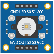
Pin Configuration and Descriptions

Pin Number Pin Name Description
1 Vdd Power supply (2.7V to 5.5V)
2 GND Ground connection
3 OE Output enable (active low)
4 OUT Output frequency (square wave)
5 S0 Output frequency scaling selection inputs
6 S1 Output frequency scaling selection inputs
7 S2 Photodiode type selection inputs
8 S3 Photodiode type selection inputs

Usage Instructions

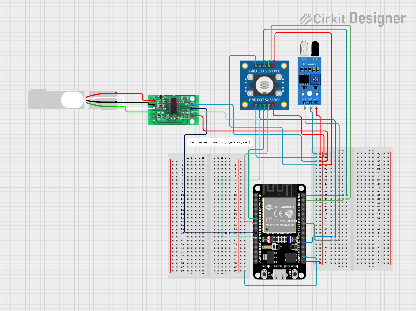
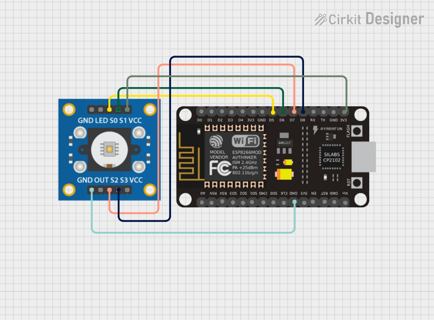
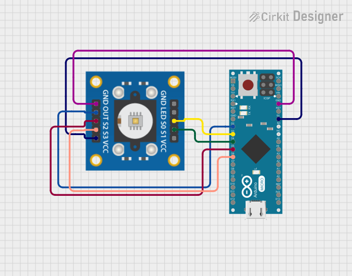
Connecting the TCS3200 to a Circuit

  1. Connect the Vdd pin to a 2.7V to 5.5V power supply.
  2. Connect the GND pin to the ground of the power supply.
  3. Connect the OE pin to ground to enable the output (or to a microcontroller pin if you wish to control it).
  4. Connect the OUT pin to a digital input on a microcontroller to read the frequency output.
  5. Use S0 and S1 pins to set the output frequency scaling (see the table below).
  6. Use S2 and S3 pins to select the photodiode type (see the table below).

Output Frequency Scaling (S0 and S1)

S0 S1 Output Frequency Scaling
L L Power down
L H 2%
H L 20%
H H 100%

Photodiode Type Selection (S2 and S3)

S2 S3 Photodiode Type
L L Red
L H Blue
H L Clear (no filter)
H H Green

Important Considerations and Best Practices

  • Ensure that the power supply voltage does not exceed 5.5V to prevent damage.
  • Use capacitors for power supply decoupling to minimize noise.
  • Avoid exposing the sensor to direct sunlight or other strong light sources that may saturate the photodiodes.
  • Calibrate the sensor for the specific application environment to achieve accurate color detection.

Example Code for Arduino UNO

// TCS3200 Color Sensor Example for Arduino UNO
#include <Wire.h>

// Define the pin connections
const int S0 = 4;
const int S1 = 5;
const int S2 = 6;
const int S3 = 7;
const int OUT = 8;

void setup() {
  pinMode(S0, OUTPUT);
  pinMode(S1, OUTPUT);
  pinMode(S2, OUTPUT);
  pinMode(S3, OUTPUT);
  pinMode(OUT, INPUT);

  // Set frequency scaling to 20%
  digitalWrite(S0, HIGH);
  digitalWrite(S1, LOW);

  Serial.begin(9600);
}

void loop() {
  // Select red photodiode
  digitalWrite(S2, LOW);
  digitalWrite(S3, LOW);
  // Read the output frequency
  int frequency = pulseIn(OUT, LOW);
  Serial.print("Red Frequency: ");
  Serial.println(frequency);

  // Add similar blocks for blue and green photodiodes
  // ...

  delay(1000); // Wait for 1 second before the next reading
}

Troubleshooting and FAQs

Common Issues

  • Sensor not responding: Ensure that all connections are secure and the power supply is within the specified range.
  • Inaccurate color readings: Calibrate the sensor for the lighting conditions of the environment.
  • No output signal: Check if the OE pin is pulled low to enable the output.

Solutions and Tips for Troubleshooting

  • If the sensor is not responding, check the power supply and connections.
  • For inaccurate readings, adjust the frequency scaling and calibrate the sensor.
  • Ensure that the OE pin is connected properly if there is no output signal.

FAQs

Q: Can the TCS3200 sensor detect non-visible light? A: No, the TCS3200 is designed to detect visible light only.

Q: How can I improve the accuracy of the sensor? A: Use frequency scaling and calibration to match the sensor's response to the application's requirements.

Q: What is the purpose of the OE pin? A: The OE (Output Enable) pin allows the user to turn the output on or off, which can be useful for power saving or multiplexing the sensor with others.

Remember to always refer to the manufacturer's datasheet for the most detailed and specific information about the TCS3200 color sensor.