Cirkit Designer Logo
Cirkit Designer
Your all-in-one circuit design IDE
Home / 
Component Documentation

How to Use LED DOT DISPLAY: Examples, Pinouts, and Specs

Image of LED DOT DISPLAY
Cirkit Designer LogoDesign with LED DOT DISPLAY in Cirkit Designer

Introduction

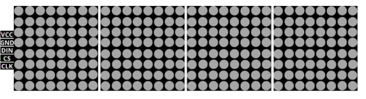
An LED Dot Display is a versatile electronic component that consists of a matrix of LEDs arranged to form characters, symbols, or graphics. Each LED acts as a pixel, which can be individually controlled to create a wide range of visual patterns. These displays are commonly used in public signage, clocks, instrument panels, and other devices where visual information needs to be conveyed simply and effectively.

Explore Projects Built with LED DOT DISPLAY

Use Cirkit Designer to design, explore, and prototype these projects online. Some projects support real-time simulation. Click "Open Project" to start designing instantly!
ESP32-Based Display Interface with Battery Management
Image of teacher project: A project utilizing LED DOT DISPLAY in a practical application
This circuit is designed to manage power from batteries and display information using an LCD and an LED dot display. It features power regulation through step-up boost converters and charging modules for the batteries, with control and data interfaces provided by two ESP32 microcontrollers for the displays.
Cirkit Designer LogoOpen Project in Cirkit Designer
ESP8266 NodeMCU Controlled LED Display with TP4056 Battery Charging
Image of virtual scrolling led display: A project utilizing LED DOT DISPLAY in a practical application
This circuit features an ESP8266 NodeMCU microcontroller connected to a LED dot display for visual output. The NodeMCU controls the display via digital pins D5, D7, and D8, which are connected to the display's CLK, DIN, and CS pins, respectively. Power management is handled by a TP4056 charging module, which charges a connected battery pack and provides power to both the NodeMCU and the LED display.
Cirkit Designer LogoOpen Project in Cirkit Designer
Arduino Nano-Controlled LED Display with RTC and Humidity Sensing
Image of Alarm Clock: A project utilizing LED DOT DISPLAY in a practical application
This circuit features a Nano 3.0 ATmega328P microcontroller connected to an LED dot display, a real-time clock (RTC DS3231), and a humidity and temperature sensor (SHT21). The microcontroller communicates with the RTC and SHT21 via I2C (using A4 and A5 as SDA and SCL lines, respectively), and it controls the LED display through SPI-like signals (using D10, D11, and D12 for DIN, CS, and CLK). The circuit is designed to display time and environmental data on the LED display, with all components sharing a common power supply and ground.
Cirkit Designer LogoOpen Project in Cirkit Designer
Wi-Fi Controlled RGB LED and OLED Display with ESP8266
Image of ESP thermometer reciever: A project utilizing LED DOT DISPLAY in a practical application
This circuit features an ESP8266 microcontroller interfaced with a 128x64 OLED display via I2C for visual output and an RGB LED controlled through current-limiting resistors. The ESP8266 provides power and control signals to both the display and the LED, enabling visual feedback and status indication.
Cirkit Designer LogoOpen Project in Cirkit Designer

Explore Projects Built with LED DOT DISPLAY

Use Cirkit Designer to design, explore, and prototype these projects online. Some projects support real-time simulation. Click "Open Project" to start designing instantly!
Image of teacher project: A project utilizing LED DOT DISPLAY in a practical application
ESP32-Based Display Interface with Battery Management
This circuit is designed to manage power from batteries and display information using an LCD and an LED dot display. It features power regulation through step-up boost converters and charging modules for the batteries, with control and data interfaces provided by two ESP32 microcontrollers for the displays.
Cirkit Designer LogoOpen Project in Cirkit Designer
Image of virtual scrolling led display: A project utilizing LED DOT DISPLAY in a practical application
ESP8266 NodeMCU Controlled LED Display with TP4056 Battery Charging
This circuit features an ESP8266 NodeMCU microcontroller connected to a LED dot display for visual output. The NodeMCU controls the display via digital pins D5, D7, and D8, which are connected to the display's CLK, DIN, and CS pins, respectively. Power management is handled by a TP4056 charging module, which charges a connected battery pack and provides power to both the NodeMCU and the LED display.
Cirkit Designer LogoOpen Project in Cirkit Designer
Image of Alarm Clock: A project utilizing LED DOT DISPLAY in a practical application
Arduino Nano-Controlled LED Display with RTC and Humidity Sensing
This circuit features a Nano 3.0 ATmega328P microcontroller connected to an LED dot display, a real-time clock (RTC DS3231), and a humidity and temperature sensor (SHT21). The microcontroller communicates with the RTC and SHT21 via I2C (using A4 and A5 as SDA and SCL lines, respectively), and it controls the LED display through SPI-like signals (using D10, D11, and D12 for DIN, CS, and CLK). The circuit is designed to display time and environmental data on the LED display, with all components sharing a common power supply and ground.
Cirkit Designer LogoOpen Project in Cirkit Designer
Image of ESP thermometer reciever: A project utilizing LED DOT DISPLAY in a practical application
Wi-Fi Controlled RGB LED and OLED Display with ESP8266
This circuit features an ESP8266 microcontroller interfaced with a 128x64 OLED display via I2C for visual output and an RGB LED controlled through current-limiting resistors. The ESP8266 provides power and control signals to both the display and the LED, enabling visual feedback and status indication.
Cirkit Designer LogoOpen Project in Cirkit Designer

Common Applications and Use Cases

  • Digital clocks and timers
  • Electronic scoreboards
  • Advertising displays
  • Information kiosks
  • Industrial control panels

Technical Specifications

Key Technical Details

  • Operating Voltage: Typically 3.3V to 5V
  • Current Consumption: Depends on the number of LEDs lit and brightness level
  • Brightness: Adjustable via current limiting or PWM control
  • Display Colors: Single color, bi-color, or RGB, depending on the model
  • Viewing Angle: Varies with LED type, often around 120 degrees

Pin Configuration and Descriptions

Pin Number Description Notes
1 Anode/Cathode Row 1 Connect to power/ground
2 Anode/Cathode Row 2 Connect to power/ground
... ... ...
n Anode/Cathode Column Connect to microcontroller pins

Note: The actual pin configuration will vary based on the specific LED dot display model. Refer to the manufacturer's datasheet for exact details.
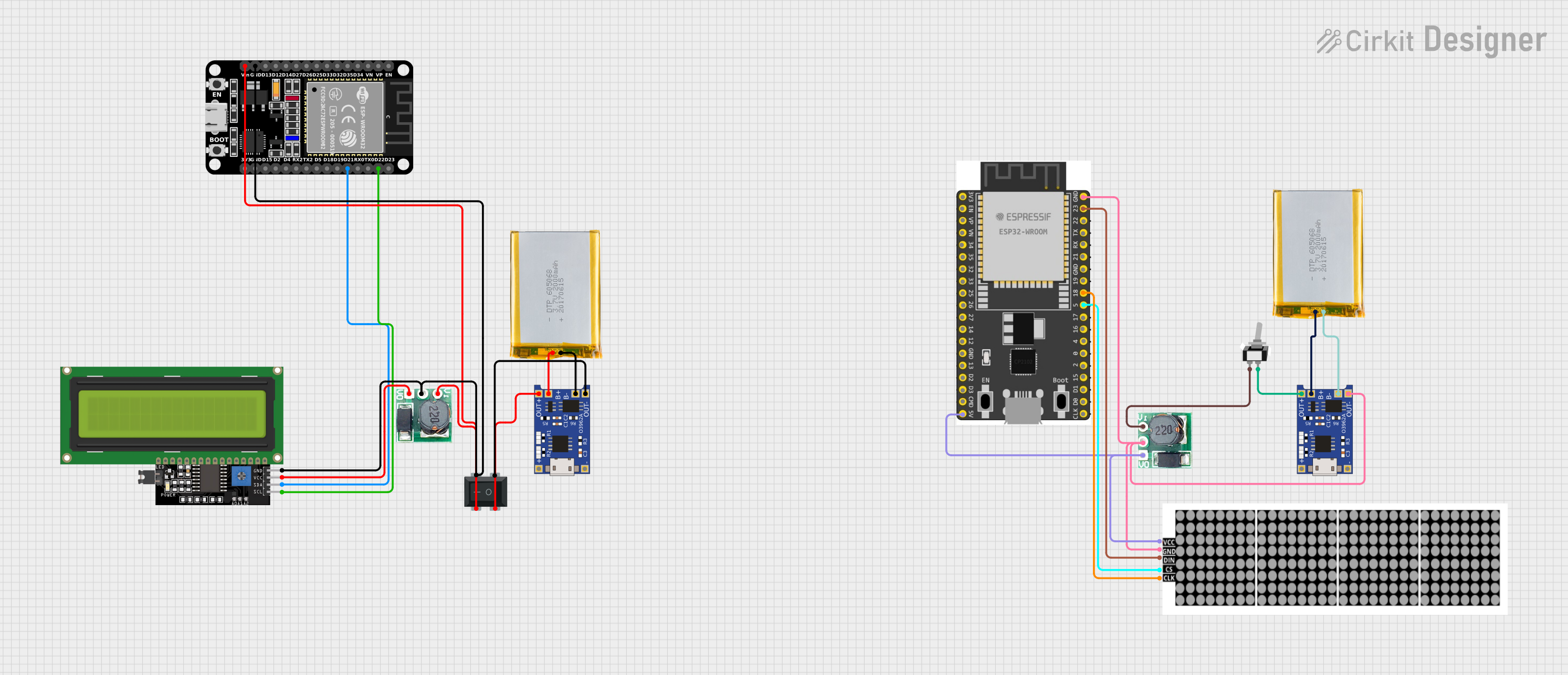
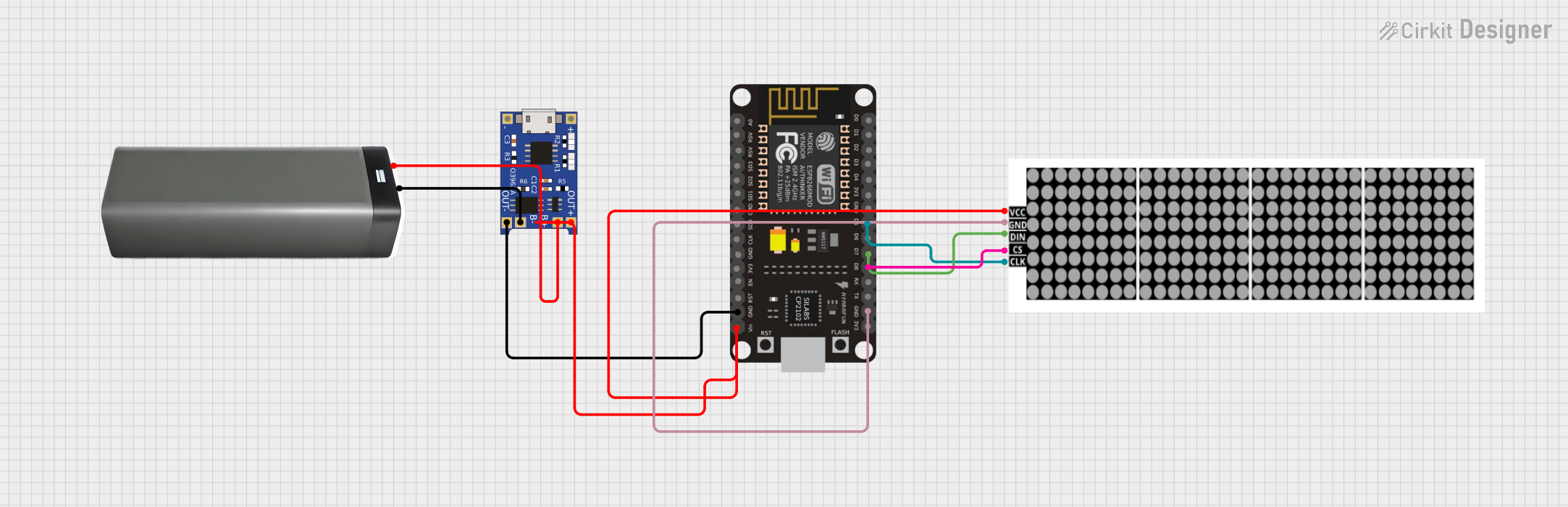
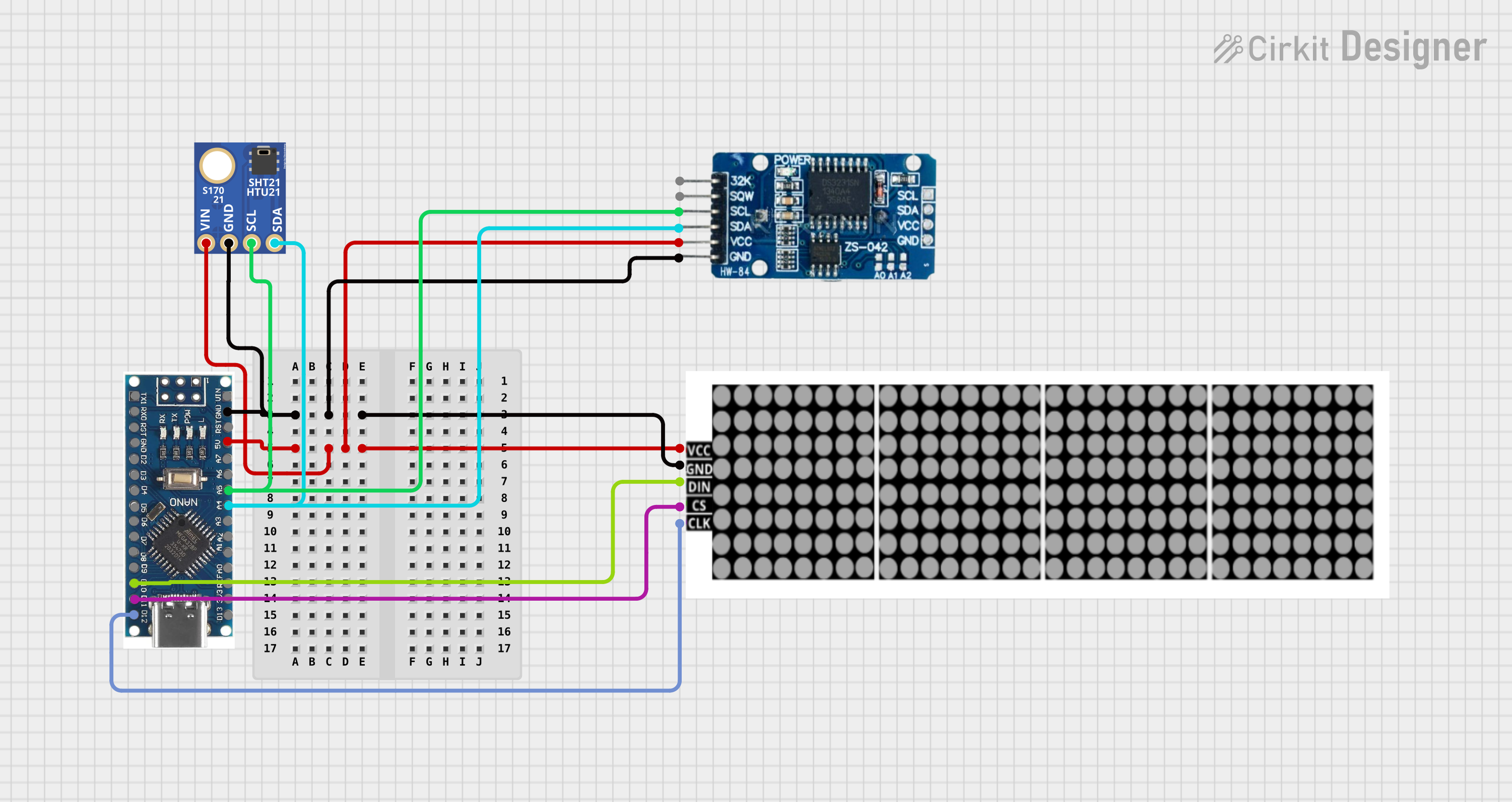
Usage Instructions

How to Use the Component in a Circuit

  1. Power Supply: Ensure that the power supply matches the voltage requirements of the LED dot display.
  2. Current Limiting: Use appropriate resistors or current sources to limit the current through each LED to prevent damage.
  3. Microcontroller Interface: Connect the rows and columns to the microcontroller's digital output pins.
  4. Multiplexing: To control a matrix, you may need to implement multiplexing in your software to manage individual LEDs.

Important Considerations and Best Practices

  • Resistor Selection: Calculate the current limiting resistors based on the forward voltage and desired current for the LEDs.
  • Refresh Rate: When multiplexing, ensure a high refresh rate to avoid flickering.
  • Brightness Control: Use PWM (Pulse Width Modulation) for brightness control if needed.
  • Heat Dissipation: Provide adequate ventilation or heat sinks if the display generates significant heat.

Example Code for Arduino UNO

// Define the pins connected to the rows and columns of the LED dot display
const int rowPins[] = {2, 3, 4, 5}; // Example row pins
const int colPins[] = {6, 7, 8, 9}; // Example column pins

void setup() {
  // Initialize all the row and column pins as outputs
  for (int i = 0; i < 4; i++) {
    pinMode(rowPins[i], OUTPUT);
    pinMode(colPins[i], OUTPUT);
  }
}

void loop() {
  // Example: Turn on each LED in a sequential pattern
  for (int row = 0; row < 4; row++) {
    for (int col = 0; col < 4; col++) {
      // Activate the current row
      digitalWrite(rowPins[row], HIGH);
      // Turn on the current LED in the column
      digitalWrite(colPins[col], LOW); // Assuming common anode configuration
      delay(100); // Keep the LED on for a short period
      // Turn off the LED
      digitalWrite(colPins[col], HIGH);
      // Deactivate the row
      digitalWrite(rowPins[row], LOW);
    }
  }
}

Note: The above code assumes a common anode configuration where the rows are connected to the anodes and the columns to the cathodes. Adjust the code accordingly if your display has a common cathode configuration.

Troubleshooting and FAQs

Common Issues Users Might Face

  • LEDs Not Lighting Up: Check the power supply and ensure that the current limiting resistors are correctly calculated and installed.
  • Flickering Display: Increase the refresh rate in your multiplexing code.
  • Dim Display: Ensure that the power supply is adequate and that PWM is correctly configured for brightness control.

Solutions and Tips for Troubleshooting

  • Verify Connections: Double-check all wiring against the circuit diagram.
  • Test Individual LEDs: Light up each LED separately to isolate any issues with specific rows or columns.
  • Code Review: Look for errors in the multiplexing logic or PWM setup in your code.

FAQs

Q: Can I use a 9V battery to power the LED dot display? A: It is not recommended to use a 9V battery directly as it exceeds the typical operating voltage. Use a voltage regulator to step down the voltage.

Q: How many pins do I need on my microcontroller to control an LED dot display? A: The number of pins required depends on the size of the matrix. For an 8x8 display, you would need 16 pins (8 for rows and 8 for columns), unless you use additional components like shift registers to reduce the number of required pins.

Q: Can I display multiple colors on a single LED dot display? A: Yes, if the display is RGB or bi-color, you can control the individual colors to mix and create different colors. However, this requires more complex control and additional pins or drivers.