How to Use С2000-СП2: Examples, Pinouts, and Specs
Introduction
The С2000-СП2, manufactured by Bolid, is a programmable logic controller (PLC) designed for industrial automation applications. It is widely used for controlling machinery, processes, and systems in manufacturing, energy management, and other industrial environments. The С2000-СП2 features a modular design, enabling users to expand its functionality by integrating additional input/output (I/O) modules. This flexibility makes it suitable for a wide range of automation tasks, from simple control systems to complex industrial processes.
Explore Projects Built with С2000-СП2


Explore Projects Built with С2000-СП2
Common Applications and Use Cases
- Industrial machinery control
- Process automation in manufacturing plants
- Energy management and monitoring systems
- Building automation (e.g., HVAC, lighting control)
- Integration with SCADA systems for real-time monitoring and control
Technical Specifications
Key Technical Details
| Parameter | Specification |
|---|---|
| Manufacturer | Bolid |
| Model | С2000-СП2 |
| Power Supply Voltage | 24V DC |
| Power Consumption | ≤ 5W |
| Operating Temperature Range | -10°C to +50°C |
| Communication Interfaces | RS-485, Ethernet |
| Supported Protocols | Modbus RTU, Modbus TCP |
| I/O Module Compatibility | Supports various digital and analog I/O modules |
| Dimensions | 120mm x 90mm x 60mm |
| Mounting Type | DIN rail |
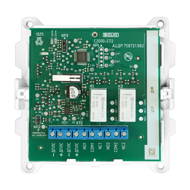
Pin Configuration and Descriptions
The С2000-СП2 features a modular design, and its pin configuration depends on the connected I/O modules. Below is a general description of the main interface pins:
| Pin Number | Pin Name | Description |
|---|---|---|
| 1 | +24V | Positive terminal for 24V DC power supply |
| 2 | GND | Ground terminal |
| 3 | RS-485 A | RS-485 communication line (A) |
| 4 | RS-485 B | RS-485 communication line (B) |
| 5 | Ethernet TX+ | Ethernet transmit line (positive) |
| 6 | Ethernet TX- | Ethernet transmit line (negative) |
| 7 | Ethernet RX+ | Ethernet receive line (positive) |
| 8 | Ethernet RX- | Ethernet receive line (negative) |
Usage Instructions
How to Use the С2000-СП2 in a Circuit
- Power Supply Connection: Connect a 24V DC power supply to the +24V and GND terminals. Ensure the power supply is stable and within the specified voltage range.
- Communication Setup:
- For RS-485 communication, connect the A and B lines to the corresponding terminals of the communication network.
- For Ethernet communication, connect the Ethernet TX and RX lines to a compatible Ethernet switch or router.
- I/O Module Integration: Attach compatible digital or analog I/O modules to the С2000-СП2. Follow the manufacturer's guidelines for module installation and wiring.
- Programming: Use the Bolid programming software to configure the PLC. Write and upload the control logic to the device via the RS-485 or Ethernet interface.
- Testing and Deployment: Test the system to ensure proper operation. Deploy the PLC in the desired industrial environment.
Important Considerations and Best Practices
- Power Supply: Use a regulated 24V DC power supply to avoid voltage fluctuations that could damage the device.
- Grounding: Ensure proper grounding to minimize electrical noise and improve communication reliability.
- Communication Protocols: Verify that the connected devices support Modbus RTU or Modbus TCP for seamless integration.
- Environmental Conditions: Install the PLC in an environment within the specified temperature range (-10°C to +50°C) and protect it from dust, moisture, and vibrations.
- Firmware Updates: Regularly check for firmware updates from Bolid to ensure optimal performance and security.
Example Code for Arduino UNO Integration
The С2000-СП2 can communicate with an Arduino UNO via the Modbus RTU protocol over RS-485. Below is an example code snippet for setting up communication:
#include <ModbusMaster.h>

// Instantiate ModbusMaster object
ModbusMaster node;

// Define RS-485 communication pins
#define RS485_TX 2  // Arduino TX pin connected to RS-485 driver
#define RS485_RX 3  // Arduino RX pin connected to RS-485 driver
#define RS485_DE 4  // Driver enable pin

void preTransmission() {
  digitalWrite(RS485_DE, HIGH); // Enable RS-485 driver for transmission
}

void postTransmission() {
  digitalWrite(RS485_DE, LOW);  // Disable RS-485 driver after transmission
}

void setup() {
  // Initialize RS-485 communication
  pinMode(RS485_DE, OUTPUT);
  digitalWrite(RS485_DE, LOW);
  Serial.begin(9600); // Set baud rate for RS-485 communication
  node.begin(1, Serial); // Set Modbus slave ID to 1
  node.preTransmission(preTransmission);
  node.postTransmission(postTransmission);
}

void loop() {
  uint8_t result;
  uint16_t data;

  // Read a register from the С2000-СП2
  result = node.readHoldingRegisters(0x0001, 1); // Read register at address 0x0001
  if (result == node.ku8MBSuccess) {
    data = node.getResponseBuffer(0); // Get the value of the register
    Serial.print("Register Value: ");
    Serial.println(data);
  } else {
    Serial.println("Communication Error");
  }

  delay(1000); // Wait 1 second before the next request
}
Troubleshooting and FAQs
Common Issues and Solutions
No Power to the Device
- Cause: Incorrect power supply connection or insufficient voltage.
- Solution: Verify the power supply voltage and connections. Ensure the power supply provides 24V DC.
Communication Failure
- Cause: Incorrect wiring or mismatched communication settings.
- Solution: Check the RS-485 or Ethernet connections. Ensure the baud rate, slave ID, and protocol settings match between the С2000-СП2 and the connected device.
I/O Modules Not Detected
- Cause: Improper installation or incompatible modules.
- Solution: Reinstall the modules and ensure they are compatible with the С2000-СП2.
Overheating
- Cause: Installation in an environment exceeding the temperature range.
- Solution: Relocate the device to a cooler environment or improve ventilation.
FAQs
Q: Can the С2000-СП2 be used with third-party I/O modules?
A: Yes, as long as the modules are compatible with the device's communication protocols and electrical specifications.Q: How do I update the firmware?
A: Use the Bolid programming software to upload the latest firmware via the RS-485 or Ethernet interface.Q: What is the maximum communication distance for RS-485?
A: The maximum distance is approximately 1200 meters, depending on the cable quality and baud rate.Q: Can the С2000-СП2 operate in outdoor environments?
A: The device is not designed for direct outdoor use. It should be installed in a protective enclosure if used outdoors.