
How to Use RN171: Examples, Pinouts, and Specs
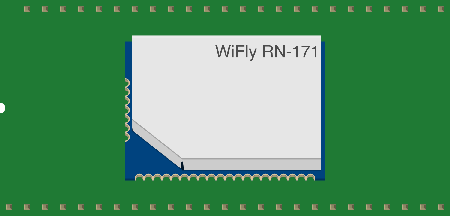
 Design with RN171 in Cirkit Designer
Introduction
The RN171 is a low-power, compact Wi-Fi module designed for embedded applications, enabling wireless connectivity for microcontrollers and other devices. It supports various networking protocols, including TCP/IP, UDP, FTP, and HTTP, making it a versatile choice for wireless communication. The module is pre-certified for FCC, IC, and CE, simplifying the integration process for developers. Its small form factor and low power consumption make it ideal for Internet of Things (IoT) projects, smart home devices, industrial automation, and other embedded systems requiring wireless connectivity.
Explore Projects Built with RN171
 Open Project in Cirkit Designer
 Open Project in Cirkit Designer
 Open Project in Cirkit Designer
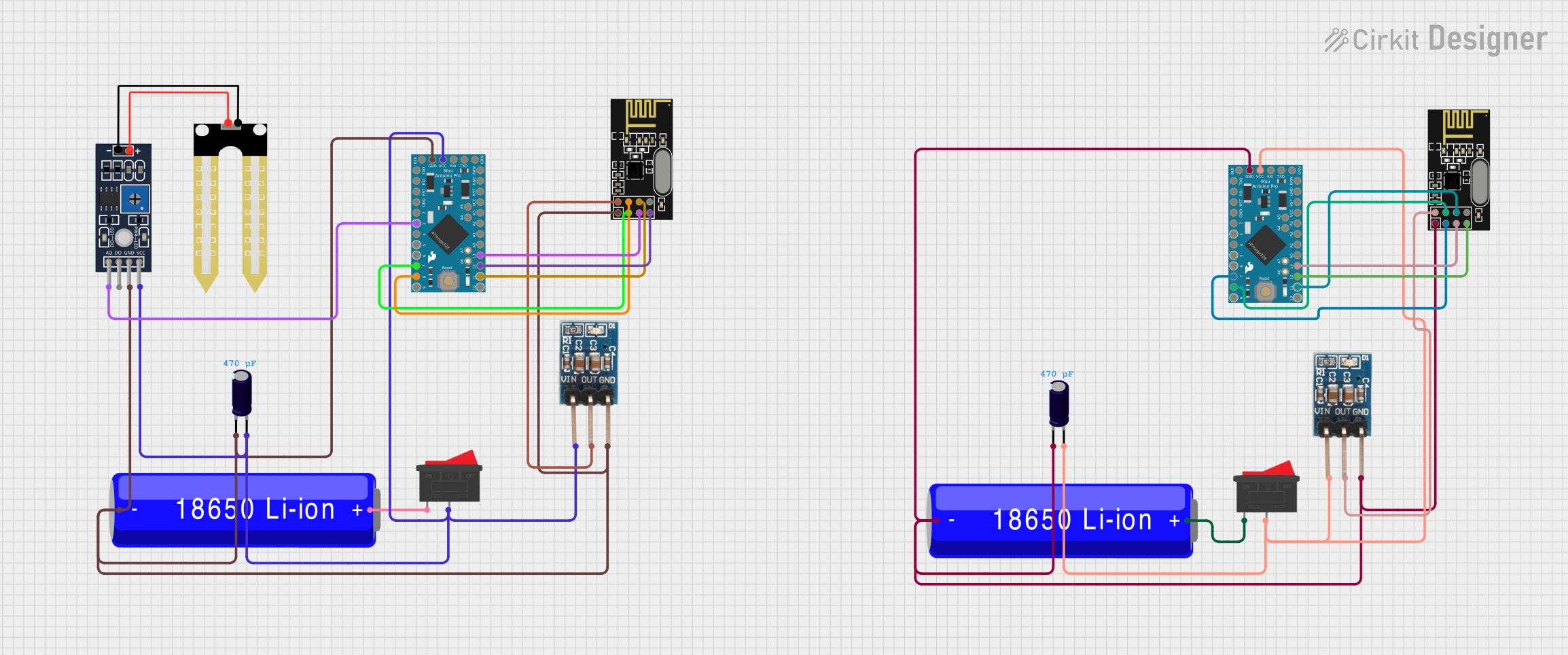 Open Project in Cirkit Designer
Explore Projects Built with RN171
Open Project in Cirkit DesignerOpen Project in Cirkit DesignerOpen Project in Cirkit DesignerOpen Project in Cirkit DesignerCommon Applications and Use Cases
- IoT devices and smart home systems
- Wireless sensor networks
- Industrial automation and monitoring
- Remote data logging and control
- Embedded systems requiring Wi-Fi connectivity
Technical Specifications
The RN171 module is designed to provide reliable wireless communication with minimal power consumption. Below are its key technical details:
Key Technical Details
- Wi-Fi Standards: IEEE 802.11b/g
- Frequency Range: 2.4 GHz
- Data Rate: Up to 54 Mbps
- Operating Voltage: 3.0V to 3.7V
- Current Consumption:
- Sleep Mode: 4 µA
- Idle Mode: 38 mA
- Transmit Mode: 210 mA (peak)
- Operating Temperature: -40°C to +85°C
- Dimensions: 26.7 mm x 17.8 mm x 3.1 mm
- Security Protocols: WEP, WPA-PSK, WPA2-PSK
- Networking Protocols: TCP/IP, UDP, FTP, HTTP
- Antenna: Integrated PCB antenna or external antenna via U.FL connector
Pin Configuration and Descriptions
The RN171 module has a 12-pin interface. Below is the pin configuration and description:
| Pin | Name | Type | Description |
|---|---|---|---|
| 1 | GND | Power | Ground connection |
| 2 | VDD | Power | Power supply input (3.0V to 3.7V) |
| 3 | TX | Output | UART Transmit (data output) |
| 4 | RX | Input | UART Receive (data input) |
| 5 | GPIO0 | Input/Output | General-purpose I/O pin |
| 6 | GPIO1 | Input/Output | General-purpose I/O pin |
| 7 | GPIO2 | Input/Output | General-purpose I/O pin |
| 8 | GPIO3 | Input/Output | General-purpose I/O pin |
| 9 | RESET | Input | Active-low reset pin |
| 10 | RTS | Output | UART Ready-to-Send signal |
| 11 | CTS | Input | UART Clear-to-Send signal |
| 12 | ADC0 | Input | Analog-to-digital converter input |
Usage Instructions
The RN171 module is straightforward to use and can be integrated into a variety of circuits. Below are the steps and best practices for using the module:
How to Use the RN171 in a Circuit
- Power Supply: Connect the VDD pin to a regulated 3.3V power source and the GND pin to ground.
- UART Communication: Connect the TX and RX pins to the UART pins of your microcontroller. Ensure proper voltage levels for UART communication.
- Reset: Use the RESET pin to initialize the module. Pull the pin low momentarily to reset the module.
- GPIO Pins: Configure the GPIO pins as needed for your application. These can be used for input or output.
- Antenna: Use the integrated PCB antenna for basic applications or connect an external antenna via the U.FL connector for extended range.
Important Considerations and Best Practices
- Power Supply: Ensure a stable 3.3V power supply to avoid damage to the module.
- UART Voltage Levels: Use a level shifter if your microcontroller operates at 5V logic levels.
- Antenna Placement: For optimal performance, place the module away from metal surfaces and other sources of interference.
- Firmware Updates: Periodically check for firmware updates from the manufacturer to ensure compatibility and security.
Example: Connecting RN171 to Arduino UNO
The RN171 can be connected to an Arduino UNO for wireless communication. Below is an example of how to set up the module and send data over Wi-Fi.
Wiring Diagram
- RN171 TX → Arduino RX (Pin 0)
- RN171 RX → Arduino TX (Pin 1)
- RN171 VDD → 3.3V on Arduino
- RN171 GND → GND on Arduino
Arduino Code
#include <SoftwareSerial.h>

// Define RX and TX pins for SoftwareSerial
SoftwareSerial wifi(2, 3); // RX = Pin 2, TX = Pin 3

void setup() {
  Serial.begin(9600); // Start Serial Monitor communication
  wifi.begin(9600);   // Start communication with RN171 module

  // Send initialization commands to RN171
  wifi.println("set wlan ssid YourSSID"); // Set Wi-Fi SSID
  wifi.println("set wlan pass YourPassword"); // Set Wi-Fi password
  wifi.println("join"); // Connect to the Wi-Fi network

  Serial.println("RN171 initialized and connected to Wi-Fi.");
}

void loop() {
  // Send data to RN171
  wifi.println("Hello from Arduino!");

  // Check for incoming data from RN171
  if (wifi.available()) {
    String data = wifi.readString();
    Serial.println("Received from RN171: " + data);
  }

  delay(1000); // Wait 1 second before sending the next message
}
Troubleshooting and FAQs
Common Issues and Solutions
Module Not Responding:
- Ensure the module is powered correctly (3.3V).
- Check the UART connections and ensure the correct baud rate is set (default: 9600 bps).
- Verify that the RESET pin is not held low.
Wi-Fi Connection Fails:
- Double-check the SSID and password for your Wi-Fi network.
- Ensure the Wi-Fi network operates on the 2.4 GHz band (the RN171 does not support 5 GHz).
Poor Signal Strength:
- Ensure the module is placed away from interference sources.
- Use an external antenna if the integrated antenna is insufficient.
Data Transmission Issues:
- Verify that the UART voltage levels match between the RN171 and the microcontroller.
- Check for loose or incorrect wiring.
FAQs
Q: Can the RN171 operate on a 5V power supply?
A: No, the RN171 requires a regulated 3.3V power supply. Using 5V can damage the module.
Q: Does the RN171 support encryption?
A: Yes, the RN171 supports WEP, WPA-PSK, and WPA2-PSK encryption protocols.
Q: Can I update the firmware on the RN171?
A: Yes, firmware updates can be performed via the UART interface. Refer to the manufacturer's documentation for detailed instructions.
Q: What is the maximum range of the RN171?
A: The range depends on the environment and antenna used. With the integrated antenna, the range is typically up to 100 meters in open space.