How to Use High-Power Stepper Motor Driver 36v4: Examples, Pinouts, and Specs
Introduction
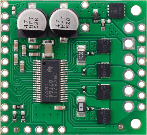
The Pololu High-Power Stepper Motor Driver 36v4 (DRV8711) is a high-performance driver designed to control stepper motors with precision and efficiency. It supports a maximum operating voltage of 36V and can deliver high current, making it suitable for demanding applications. The driver is based on the Texas Instruments DRV8711 stepper motor driver IC, which provides advanced features such as configurable microstepping, current control, and fault detection.
Explore Projects Built with High-Power Stepper Motor Driver 36v4


Explore Projects Built with High-Power Stepper Motor Driver 36v4
Common Applications and Use Cases
- 3D printers and CNC machines
- Robotics and automation systems
- Precision motion control in industrial equipment
- High-torque stepper motor applications
- Prototyping and development of motorized systems
Technical Specifications
The following table outlines the key technical details of the High-Power Stepper Motor Driver 36v4:
| Parameter | Value |
|---|---|
| Operating Voltage Range | 10V to 36V |
| Maximum Output Current | 4.5A per phase (continuous) |
| Microstepping Modes | Full-step to 1/256-step |
| Logic Voltage | 3.3V or 5V (logic interface) |
| Control Interface | SPI |
| Overcurrent Protection | Yes |
| Overtemperature Protection | Yes |
| Dimensions | 1.3" × 1.0" × 0.4" (33 × 25 × 10 mm) |
Pin Configuration and Descriptions
The High-Power Stepper Motor Driver 36v4 has the following pin configuration:
| Pin Name | Type | Description |
|---|---|---|
| VM | Power Input | Motor power supply (10V to 36V). Connect to the positive terminal of the supply. |
| GND | Power Ground | Ground connection for the motor power supply. |
| STEP | Input | Step signal input for controlling motor steps. |
| DIR | Input | Direction signal input for controlling motor rotation direction. |
| SLEEP | Input | Puts the driver into a low-power sleep mode when pulled low. |
| RESET | Input | Resets the driver when pulled low. |
| SPI (SDO, SDI, SCK, CS) | Communication | SPI interface pins for configuring and monitoring the driver. |
| AOUT1, AOUT2 | Output | Outputs for motor coil A. |
| BOUT1, BOUT2 | Output | Outputs for motor coil B. |
| FAULT | Output | Indicates fault conditions (e.g., overcurrent, overtemperature). |
Usage Instructions
How to Use the Component in a Circuit
- Power Supply: Connect a DC power supply (10V to 36V) to the VM pin and GND. Ensure the power supply can provide sufficient current for your motor.
- Motor Connections: Connect the stepper motor coils to the AOUT1, AOUT2, BOUT1, and BOUT2 pins. Refer to your motor's datasheet for the correct wiring.
- Logic Connections: Connect the STEP, DIR, and other control pins to your microcontroller or control system. Use the SPI interface to configure advanced settings.
- Microstepping and Current Control: Use the SPI interface to set the desired microstepping mode and current limits. Refer to the DRV8711 datasheet for detailed configuration options.
- Enable the Driver: Ensure the SLEEP and RESET pins are pulled high to enable the driver.
Important Considerations and Best Practices
- Heat Dissipation: The driver can generate significant heat during operation. Use a heatsink or active cooling if necessary.
- Current Limiting: Set the current limit appropriately to prevent damage to the motor and driver.
- Fault Handling: Monitor the FAULT pin to detect and respond to fault conditions.
- Decoupling Capacitors: Place a suitable decoupling capacitor (e.g., 100 µF) near the VM pin to stabilize the power supply.
Example: Using with Arduino UNO
Below is an example of how to control the High-Power Stepper Motor Driver 36v4 with an Arduino UNO:
#include <SPI.h>

// Pin definitions
#define CS_PIN 10  // Chip Select pin for SPI
#define STEP_PIN 3 // Step signal pin
#define DIR_PIN 4  // Direction signal pin

void setup() {
  // Initialize SPI
  SPI.begin();
  pinMode(CS_PIN, OUTPUT);
  digitalWrite(CS_PIN, HIGH); // Set CS pin high to disable SPI communication

  // Initialize STEP and DIR pins
  pinMode(STEP_PIN, OUTPUT);
  pinMode(DIR_PIN, OUTPUT);

  // Set initial direction
  digitalWrite(DIR_PIN, LOW); // Set direction to clockwise
}

void loop() {
  // Generate step pulses
  digitalWrite(STEP_PIN, HIGH);
  delayMicroseconds(500); // 500 µs high time
  digitalWrite(STEP_PIN, LOW);
  delayMicroseconds(500); // 500 µs low time
}
Notes:
- The SPI interface can be used to configure advanced settings such as microstepping and current limits. Refer to the DRV8711 datasheet for SPI register details.
- Ensure the motor's rated voltage and current are within the driver's specifications.
Troubleshooting and FAQs
Common Issues and Solutions
Motor Not Moving:
- Verify the power supply voltage and current are sufficient.
- Check the STEP and DIR signals from the microcontroller.
- Ensure the motor is properly connected to the driver.
Driver Overheating:
- Use a heatsink or active cooling to dissipate heat.
- Reduce the current limit via the SPI interface.
FAULT Pin Active:
- Check for overcurrent or overtemperature conditions.
- Verify the motor connections and ensure there are no short circuits.
No SPI Communication:
- Ensure the CS, SCK, SDI, and SDO pins are correctly connected.
- Verify the SPI clock speed is within the driver's specifications.
FAQs
Q: Can I use this driver with a 12V power supply?
A: Yes, the driver supports a voltage range of 10V to 36V, so a 12V power supply is compatible.
Q: What is the maximum microstepping resolution?
A: The driver supports up to 1/256-step microstepping for precise motor control.
Q: How do I set the current limit?
A: Use the SPI interface to configure the current limit registers. Refer to the DRV8711 datasheet for details.
Q: Is the driver compatible with NEMA 17 stepper motors?
A: Yes, the driver is compatible with most stepper motors, including NEMA 17, as long as the motor's voltage and current ratings are within the driver's specifications.