How to Use MRA070A 8-Channel IR Line Sensor Module: Examples, Pinouts, and Specs
Introduction
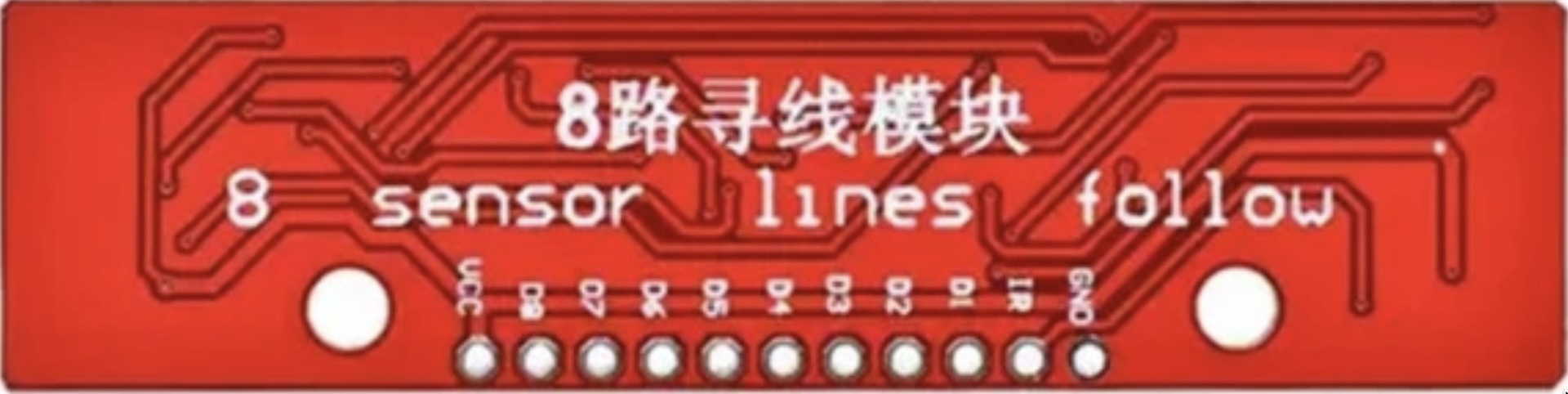
The MRA070A is an 8-channel infrared (IR) line sensor module designed for detecting lines or edges on surfaces. It uses an array of IR sensors to detect the presence of a line, typically a black line on a white surface or vice versa. This module is widely used in robotics and automation applications, such as line-following robots, edge detection, and object tracking, where precise and reliable line detection is essential.
Explore Projects Built with MRA070A 8-Channel IR Line Sensor Module


Explore Projects Built with MRA070A 8-Channel IR Line Sensor Module
Common Applications
- Line-following robots
- Edge detection in automation systems
- Object tracking and positioning
- Path navigation in autonomous vehicles
- Industrial sorting and conveyor systems
Technical Specifications
The MRA070A module is designed to provide accurate and efficient line detection. Below are its key technical details:
| Parameter | Specification |
|---|---|
| Operating Voltage | 3.3V to 5V |
| Operating Current | ~100mA |
| Number of Channels | 8 |
| Sensor Type | Infrared (IR) Reflective Sensors |
| Output Type | Digital (High/Low) |
| Detection Range | 2mm to 12mm (optimal: 3mm to 5mm) |
| Dimensions | 100mm x 15mm x 10mm |
| Weight | ~15g |
Pin Configuration and Descriptions
The MRA070A module has a 10-pin interface for power, ground, and signal outputs. Below is the pin configuration:
| Pin | Name | Description |
|---|---|---|
| 1 | VCC | Power supply input (3.3V to 5V) |
| 2 | GND | Ground connection |
| 3 | OUT1 | Digital output for sensor channel 1 |
| 4 | OUT2 | Digital output for sensor channel 2 |
| 5 | OUT3 | Digital output for sensor channel 3 |
| 6 | OUT4 | Digital output for sensor channel 4 |
| 7 | OUT5 | Digital output for sensor channel 5 |
| 8 | OUT6 | Digital output for sensor channel 6 |
| 9 | OUT7 | Digital output for sensor channel 7 |
| 10 | OUT8 | Digital output for sensor channel 8 |
Usage Instructions
How to Use the MRA070A in a Circuit
- Power the Module: Connect the
VCCpin to a 3.3V or 5V power source and theGNDpin to ground. - Connect Outputs: Each of the 8 output pins (
OUT1toOUT8) corresponds to a sensor channel. Connect these pins to the input pins of a microcontroller or other processing unit. - Position the Module: Place the module above the surface to be detected, ensuring the sensors are at an optimal height (3mm to 5mm) for accurate detection.
- Read Outputs: The output pins will provide a digital signal:
HIGH(1): No line detected (reflective surface).LOW(0): Line detected (non-reflective surface).
Important Considerations
- Surface Contrast: Ensure there is sufficient contrast between the line and the background surface for reliable detection.
- Ambient Light: Minimize ambient light interference by using the module in controlled lighting conditions or shielding it from external light sources.
- Mounting: Secure the module firmly to avoid vibrations or misalignment during operation.
- Power Supply: Use a stable power source to prevent fluctuations that could affect sensor performance.
Example: Connecting to an Arduino UNO
Below is an example of how to connect and use the MRA070A with an Arduino UNO to read sensor outputs:
Circuit Connections
- Connect
VCCto the Arduino's5Vpin. - Connect
GNDto the Arduino'sGNDpin. - Connect
OUT1toD2,OUT2toD3, and so on, up toOUT8toD9.
Arduino Code
// Define pins for the 8 sensor outputs
const int sensorPins[8] = {2, 3, 4, 5, 6, 7, 8, 9};

void setup() {
  // Initialize serial communication for debugging
  Serial.begin(9600);

  // Set sensor pins as inputs
  for (int i = 0; i < 8; i++) {
    pinMode(sensorPins[i], INPUT);
  }
}

void loop() {
  // Read and print the state of each sensor
  Serial.print("Sensor States: ");
  for (int i = 0; i < 8; i++) {
    int sensorState = digitalRead(sensorPins[i]);
    Serial.print(sensorState);
    Serial.print(" "); // Add space between sensor states
  }
  Serial.println(); // Move to the next line
  delay(100); // Small delay for readability
}
Troubleshooting and FAQs
Common Issues and Solutions
No Output Detected:
- Cause: Incorrect wiring or loose connections.
- Solution: Double-check all connections, especially
VCCandGND.
Inconsistent Readings:
- Cause: Module height is not optimal or surface contrast is insufficient.
- Solution: Adjust the module height to 3mm-5mm and ensure a clear contrast between the line and the background.
Interference from Ambient Light:
- Cause: Strong external light sources affecting IR sensors.
- Solution: Use the module in a controlled lighting environment or shield it from external light.
All Outputs Always HIGH or LOW:
- Cause: Faulty module or incorrect power supply voltage.
- Solution: Verify the power supply voltage and test the module on a known surface.
FAQs
Q1: Can the MRA070A detect colored lines?
A1: The module is optimized for detecting black lines on white surfaces or vice versa. It may not reliably detect colored lines unless there is a significant contrast.
Q2: What is the maximum detection range?
A2: The module can detect lines within a range of 2mm to 12mm, but the optimal range is 3mm to 5mm.
Q3: Can I use this module with a 3.3V microcontroller?
A3: Yes, the MRA070A supports an operating voltage of 3.3V to 5V, making it compatible with 3.3V microcontrollers like the ESP32.
Q4: How do I clean the sensors?
A4: Use a soft, lint-free cloth to gently clean the sensor lenses. Avoid using liquids or abrasive materials.
By following this documentation, you can effectively integrate the MRA070A 8-Channel IR Line Sensor Module into your projects for precise and reliable line detection.