How to Use PC817: Examples, Pinouts, and Specs

Introduction
The PC817, manufactured by SKR Electronics Lab, is an optocoupler, also known as an optoisolator. This component is designed to transfer electrical signals between two isolated circuits using light. It typically consists of an LED and a phototransistor in a single package, providing electrical isolation and protection from high voltages. Optocouplers are widely used in applications where signal isolation is crucial, such as in power supply circuits, microcontroller interfaces, and communication systems.
Explore Projects Built with PC817
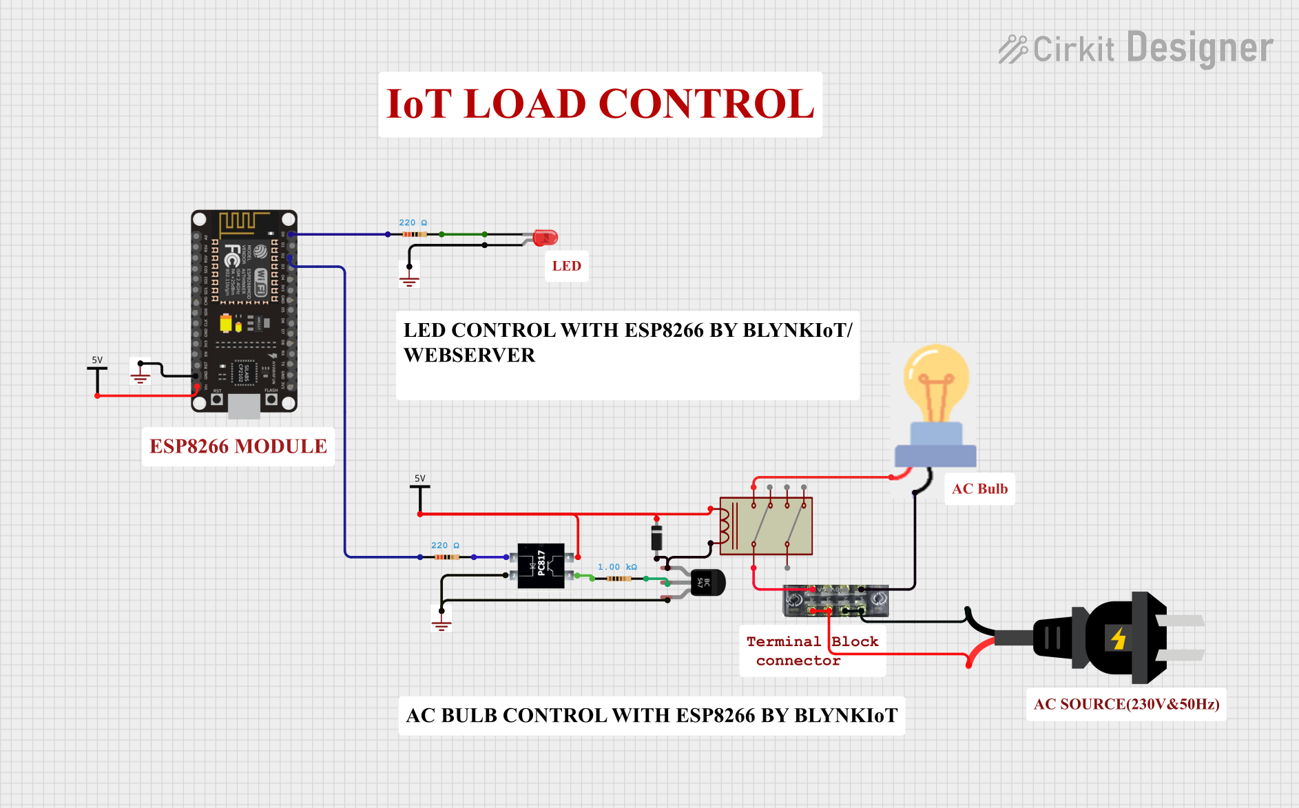
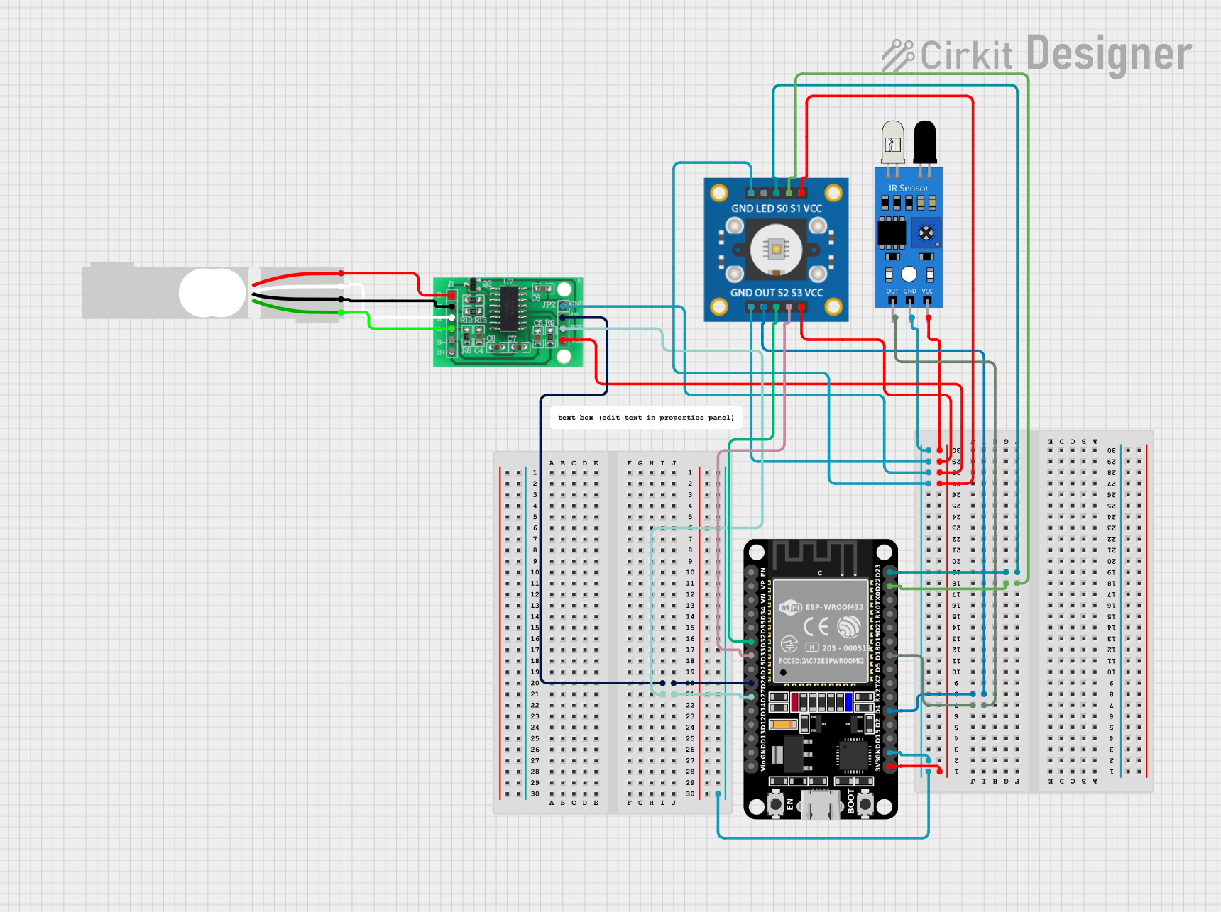
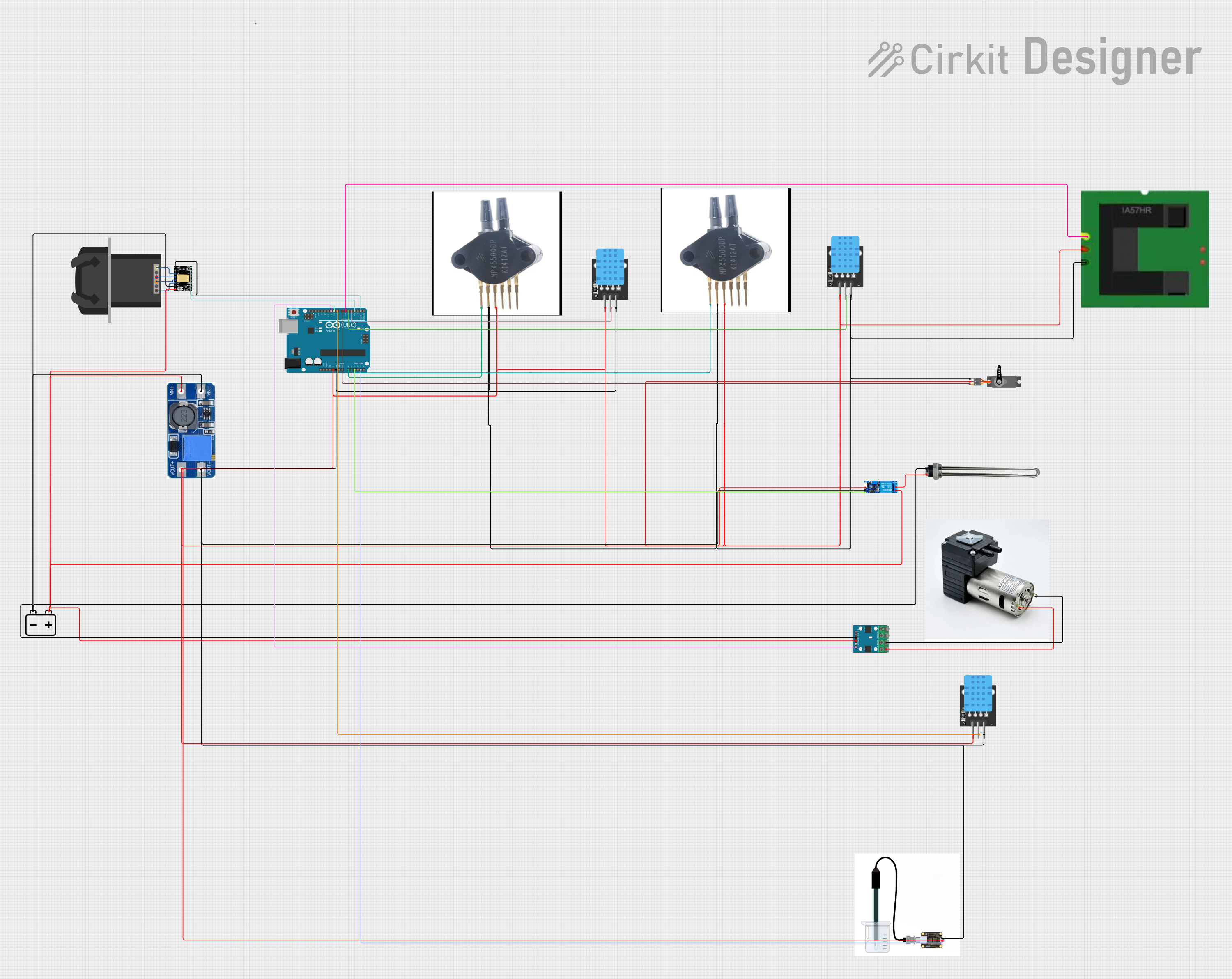

Explore Projects Built with PC817
Technical Specifications
Key Technical Details
| Parameter | Value |
|---|---|
| Manufacturer | SKR Electronics Lab |
| Part ID | PC817 |
| Isolation Voltage | 5000 Vrms |
| Forward Voltage | 1.2V (typical) |
| Forward Current | 20mA (max) |
| Collector-Emitter Voltage | 80V (max) |
| Collector Current | 50mA (max) |
| Power Dissipation | 200mW (max) |
| Operating Temperature Range | -30°C to +100°C |
Pin Configuration and Descriptions
| Pin Number | Name | Description |
|---|---|---|
| 1 | Anode | Positive terminal of the internal LED |
| 2 | Cathode | Negative terminal of the internal LED |
| 3 | Emitter | Emitter of the internal phototransistor |
| 4 | Collector | Collector of the internal phototransistor |
Usage Instructions
How to Use the PC817 in a Circuit
Connect the LED Side:
- Connect the anode (Pin 1) to the positive side of the input signal.
- Connect the cathode (Pin 2) to the ground of the input signal.
Connect the Phototransistor Side:
- Connect the collector (Pin 4) to the positive side of the output circuit.
- Connect the emitter (Pin 3) to the ground of the output circuit.
Important Considerations and Best Practices
- Current Limiting Resistor: Always use a current-limiting resistor in series with the LED to prevent it from drawing excessive current. Calculate the resistor value using Ohm's law: ( R = \frac{V_{in} - V_f}{I_f} ), where ( V_{in} ) is the input voltage, ( V_f ) is the forward voltage of the LED, and ( I_f ) is the forward current.
- Isolation: Ensure that the input and output circuits are electrically isolated to prevent high voltage from damaging sensitive components.
- Temperature: Operate the PC817 within the specified temperature range to avoid thermal damage.
Example Circuit with Arduino UNO
/*
 * Example code to demonstrate the use of PC817 optocoupler with Arduino UNO.
 * This code turns on an LED connected to the optocoupler when a button is pressed.
 */

const int buttonPin = 2;    // Pin connected to the button
const int ledPin = 13;      // Pin connected to the internal LED of Arduino
const int optoLED = 7;      // Pin connected to the anode of PC817 LED

void setup() {
  pinMode(buttonPin, INPUT);  // Set button pin as input
  pinMode(ledPin, OUTPUT);    // Set LED pin as output
  pinMode(optoLED, OUTPUT);   // Set optoLED pin as output
}

void loop() {
  int buttonState = digitalRead(buttonPin);  // Read the state of the button

  if (buttonState == HIGH) {
    digitalWrite(optoLED, HIGH);  // Turn on the optocoupler LED
    digitalWrite(ledPin, HIGH);   // Turn on the Arduino LED
  } else {
    digitalWrite(optoLED, LOW);   // Turn off the optocoupler LED
    digitalWrite(ledPin, LOW);    // Turn off the Arduino LED
  }
}
Troubleshooting and FAQs
Common Issues and Solutions
LED Not Turning On:
- Check Connections: Ensure that all connections are secure and correct.
- Current Limiting Resistor: Verify that the current-limiting resistor is of the correct value.
- Input Voltage: Ensure that the input voltage is sufficient to forward bias the LED.
No Output Signal:
- Phototransistor Connections: Ensure that the collector and emitter are correctly connected.
- Isolation: Verify that the input and output circuits are properly isolated.
Overheating:
- Current Limiting: Ensure that the current through the LED does not exceed the maximum rating.
- Ambient Temperature: Operate the PC817 within the specified temperature range.
FAQs
Q1: Can the PC817 be used for AC signal isolation? A1: Yes, the PC817 can be used for AC signal isolation, but ensure that the LED is properly biased and protected against reverse voltage.
Q2: What is the maximum switching speed of the PC817? A2: The PC817 has a typical switching speed of around 3µs, making it suitable for many low to moderate speed applications.
Q3: Can I use the PC817 to interface with a microcontroller? A3: Yes, the PC817 is commonly used to interface microcontrollers with high voltage or noisy environments, providing electrical isolation and protection.
This documentation provides a comprehensive guide to using the PC817 optocoupler. By following the instructions and best practices outlined, users can effectively integrate this component into their electronic projects.