Cirkit Designer Logo
Cirkit Designer
Your all-in-one circuit design IDE
Home / 
Component Documentation

How to Use MAX30100: Examples, Pinouts, and Specs

Image of MAX30100
Cirkit Designer LogoDesign with MAX30100 in Cirkit Designer

Introduction

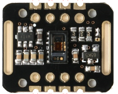
The MAX30100 is an integrated pulse oximetry and heart-rate monitor sensor solution. It combines two LEDs, a photodetector, optimized optics, and low-noise analog signal processing to detect pulse oximetry and heart-rate signals. The MAX30100 is widely used in wearable technology, fitness assistant devices, and medical monitoring equipment.

Explore Projects Built with MAX30100

Use Cirkit Designer to design, explore, and prototype these projects online. Some projects support real-time simulation. Click "Open Project" to start designing instantly!
ESP32 and MAX30100 Pulse Oximeter
Image of t: A project utilizing MAX30100 in a practical application
This circuit features an ESP32 microcontroller connected to a MAX30100 sensor, which is likely used for measuring pulse oximetry. The ESP32 is interfaced with the MAX30100 via I2C communication, as indicated by the SDA and SCL connections. Power is supplied to both the ESP32 and the MAX30100 by a 5V battery, with common ground established across the components.
Cirkit Designer LogoOpen Project in Cirkit Designer
ESP32-Based Multi-Sensor Health Monitoring System with Bluetooth Connectivity
Image of circuit diagram: A project utilizing MAX30100 in a practical application
This circuit features an ESP32-WROOM-32UE microcontroller as the central processing unit, interfacing with a variety of sensors and modules. It includes a MAX30100 pulse oximeter and heart-rate sensor, an MLX90614 infrared thermometer, an HC-05 Bluetooth module for wireless communication, and a Neo 6M GPS module for location tracking. All components are powered by a common voltage supply and are connected to specific GPIO pins on the ESP32 for data exchange, with the sensors using I2C communication and the modules using UART.
Cirkit Designer LogoOpen Project in Cirkit Designer
ESP32-Based Health Monitoring System with Bluetooth and GPS
Image of circuit diagram: A project utilizing MAX30100 in a practical application
This circuit integrates an ESP32 microcontroller with various sensors and modules, including a MAX30100 pulse oximeter, an MLX90614 infrared thermometer, a Neo 6M GPS module, and an HC-05 Bluetooth module. The ESP32 collects data from these sensors and modules via I2C and UART interfaces, enabling wireless communication and GPS tracking capabilities.
Cirkit Designer LogoOpen Project in Cirkit Designer
Wi-Fi Enabled Health Monitoring System with MAX30100 and MLX90614
Image of NEW project: A project utilizing MAX30100 in a practical application
This circuit integrates a MAX30100 pulse oximeter and heart-rate sensor, and an MLX90614 infrared temperature sensor with an ESP8266 NodeMCU microcontroller. The sensors communicate with the microcontroller via I2C protocol, and the NodeMCU provides power and handles data processing and transmission.
Cirkit Designer LogoOpen Project in Cirkit Designer

Explore Projects Built with MAX30100

Use Cirkit Designer to design, explore, and prototype these projects online. Some projects support real-time simulation. Click "Open Project" to start designing instantly!
Image of t: A project utilizing MAX30100 in a practical application
ESP32 and MAX30100 Pulse Oximeter
This circuit features an ESP32 microcontroller connected to a MAX30100 sensor, which is likely used for measuring pulse oximetry. The ESP32 is interfaced with the MAX30100 via I2C communication, as indicated by the SDA and SCL connections. Power is supplied to both the ESP32 and the MAX30100 by a 5V battery, with common ground established across the components.
Cirkit Designer LogoOpen Project in Cirkit Designer
Image of circuit diagram: A project utilizing MAX30100 in a practical application
ESP32-Based Multi-Sensor Health Monitoring System with Bluetooth Connectivity
This circuit features an ESP32-WROOM-32UE microcontroller as the central processing unit, interfacing with a variety of sensors and modules. It includes a MAX30100 pulse oximeter and heart-rate sensor, an MLX90614 infrared thermometer, an HC-05 Bluetooth module for wireless communication, and a Neo 6M GPS module for location tracking. All components are powered by a common voltage supply and are connected to specific GPIO pins on the ESP32 for data exchange, with the sensors using I2C communication and the modules using UART.
Cirkit Designer LogoOpen Project in Cirkit Designer
Image of circuit diagram: A project utilizing MAX30100 in a practical application
ESP32-Based Health Monitoring System with Bluetooth and GPS
This circuit integrates an ESP32 microcontroller with various sensors and modules, including a MAX30100 pulse oximeter, an MLX90614 infrared thermometer, a Neo 6M GPS module, and an HC-05 Bluetooth module. The ESP32 collects data from these sensors and modules via I2C and UART interfaces, enabling wireless communication and GPS tracking capabilities.
Cirkit Designer LogoOpen Project in Cirkit Designer
Image of NEW project: A project utilizing MAX30100 in a practical application
Wi-Fi Enabled Health Monitoring System with MAX30100 and MLX90614
This circuit integrates a MAX30100 pulse oximeter and heart-rate sensor, and an MLX90614 infrared temperature sensor with an ESP8266 NodeMCU microcontroller. The sensors communicate with the microcontroller via I2C protocol, and the NodeMCU provides power and handles data processing and transmission.
Cirkit Designer LogoOpen Project in Cirkit Designer

Common Applications and Use Cases

  • Wearable devices for fitness tracking
  • Health monitoring systems
  • Smartwatches with vital signs monitoring
  • Medical-grade pulse oximeters

Technical Specifications

Key Technical Details

  • Power Supply: 1.8V to 3.3V
  • Operating Temperature: -40°C to +85°C
  • Communication Interface: I2C
  • LED Wavelengths: 660nm (Red), 940nm (IR)

Pin Configuration and Descriptions

Pin Number Name Description
1 VIN Supply voltage (1.8V to 3.3V)
2 SCL I2C clock
3 SDA I2C data
4 INT Interrupt output
5 RD Red LED cathode
6 IRD IR LED cathode
7 GND Ground

Usage Instructions

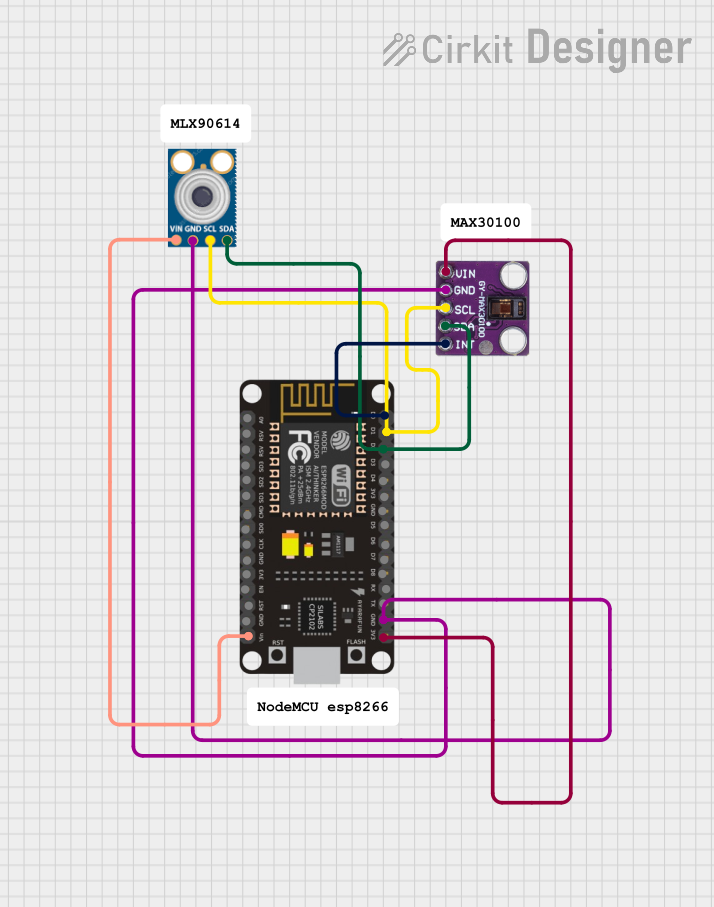
How to Use the MAX30100 in a Circuit

  1. Power Supply: Connect the VIN pin to a 1.8V to 3.3V power source and GND to the ground.
  2. I2C Communication: Connect SCL and SDA to the corresponding I2C clock and data lines on your microcontroller.
  3. Interrupts: Optionally, connect the INT pin to an interrupt-capable GPIO pin on your microcontroller.
  4. LEDs: The RD and IRD pins are internally connected to the LEDs. No external connection is required.

Important Considerations and Best Practices

  • Ensure that the power supply is stable and within the specified voltage range.
  • Use pull-up resistors on the I2C lines as required by your microcontroller's I2C interface.
  • Place the sensor close to the skin to get accurate readings.
  • Avoid direct sunlight and other strong light sources that may interfere with the sensor readings.

Example Code for Arduino UNO

#include <Wire.h>
#include "MAX30100_PulseOximeter.h"

PulseOximeter pox;
uint32_t tsLastReport = 0;

void setup() {
  Serial.begin(115200);
  if (!pox.begin()) {
    Serial.println("Failed to initialize pulse oximeter!");
    for(;;);
  } else {
    Serial.println("Pulse oximeter initialized.");
  }
}

void loop() {
  // Make sure to call update as fast as possible
  pox.update();
  if (millis() - tsLastReport > 1000) {
    Serial.print("Heart rate:");
    Serial.print(pox.getHeartRate());
    Serial.print("bpm / SpO2:");
    Serial.print(pox.getSpO2());
    Serial.println("%");

    tsLastReport = millis();
  }
}

Note: This example assumes the use of a MAX30100 library, which provides the PulseOximeter class and simplifies the interaction with the sensor.

Troubleshooting and FAQs

Common Issues

  • Inaccurate Readings: Ensure the sensor is properly placed on the skin and that there is no movement or external light interference.
  • No Data on I2C: Check the connections and pull-up resistors on the I2C lines. Also, ensure that the correct I2C address is being used.

Solutions and Tips for Troubleshooting

  • Sensor Not Detected: Verify the power supply and I2C connections. Use an I2C scanner sketch to check if the sensor is detected on the bus.
  • Fluctuating Readings: Stabilize the sensor placement and avoid direct light interference.

FAQs

Q: Can the MAX30100 be used with a 5V system? A: While the MAX30100 operates at 1.8V to 3.3V, level shifters can be used for 5V systems.

Q: How can I improve the accuracy of the sensor? A: Ensure a snug fit against the skin, minimize motion, and avoid external light interference.

Q: What is the default I2C address of the MAX30100? A: The default I2C address is 0x57 (7-bit).

Q: How do I know if the MAX30100 is functioning correctly? A: Check for a stable heart rate and SpO2 reading. If the readings are erratic, review the sensor placement and circuit connections.