How to Use METSEPM2120: Examples, Pinouts, and Specs

Introduction
The METSEPM2120, manufactured by EasyLogic, is a high-performance, low-power operational amplifier designed for precision signal processing applications. It is part of the ModbusPowerMeter series and is engineered to deliver exceptional accuracy and reliability. With its wide bandwidth, low noise, and high slew rate, the METSEPM2120 is ideal for a variety of analog signal conditioning tasks, including industrial automation, energy monitoring, and instrumentation.
Explore Projects Built with METSEPM2120

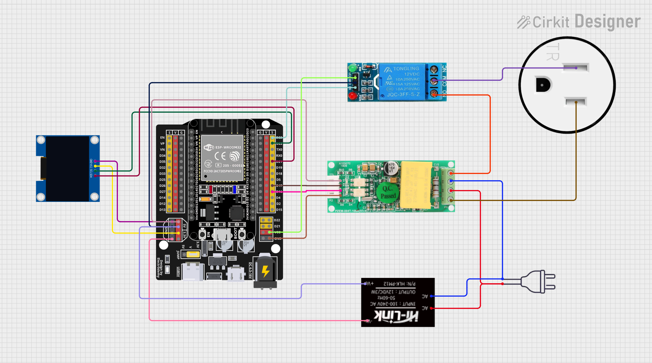
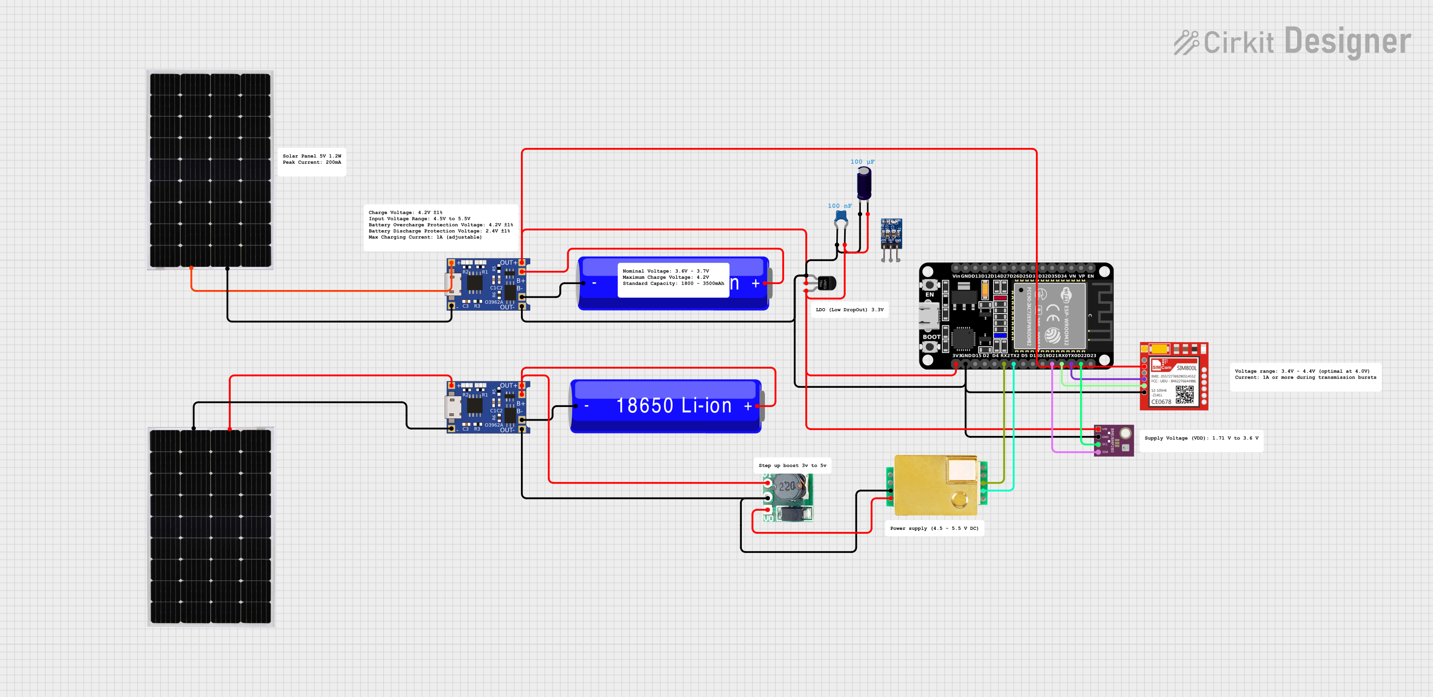

Explore Projects Built with METSEPM2120
Common Applications
- Energy monitoring and management systems
- Industrial automation and control
- Precision analog signal processing
- Data acquisition systems
- Instrumentation and measurement devices
Technical Specifications
Key Technical Details
| Parameter | Value |
|---|---|
| Manufacturer | EasyLogic |
| Part Number | METSEPM2120 |
| Series | ModbusPowerMeter |
| Supply Voltage Range | 3.3V to 5V |
| Input Offset Voltage | ±1 mV |
| Bandwidth | 10 MHz |
| Slew Rate | 5 V/µs |
| Input Noise Density | 10 nV/√Hz |
| Operating Temperature | -40°C to +85°C |
| Power Consumption | Low power (typical: 1.2 mW) |
| Communication Protocol | Modbus RTU |
Pin Configuration and Descriptions
The METSEPM2120 is typically available in an 8-pin package. Below is the pinout and description:
| Pin Number | Pin Name | Description |
|---|---|---|
| 1 | V+ | Positive power supply (3.3V to 5V) |
| 2 | IN+ | Non-inverting input |
| 3 | IN- | Inverting input |
| 4 | GND | Ground |
| 5 | OUT | Output signal |
| 6 | NC | No connection (leave unconnected) |
| 7 | V- | Negative power supply (optional, for dual-supply) |
| 8 | COM | Communication interface for Modbus RTU |
Usage Instructions
How to Use the METSEPM2120 in a Circuit
- Power Supply: Connect the V+ pin to a stable power source within the range of 3.3V to 5V. If using a dual-supply configuration, connect the V- pin to the negative voltage source.
- Input Connections: Connect the signal to be amplified to the IN+ (non-inverting) and IN- (inverting) pins. Ensure proper impedance matching for optimal performance.
- Output Signal: The amplified signal will be available at the OUT pin. Connect this pin to the next stage of your circuit.
- Grounding: Connect the GND pin to the ground of your circuit to ensure proper operation.
- Communication: Use the COM pin to interface with a Modbus RTU-compatible device for monitoring and control.
Important Considerations and Best Practices
- Decoupling Capacitors: Place decoupling capacitors (e.g., 0.1 µF and 10 µF) close to the V+ and GND pins to reduce noise and ensure stable operation.
- Input Signal Range: Ensure the input signal does not exceed the specified input voltage range to avoid distortion or damage.
- Thermal Management: Operate the component within the specified temperature range (-40°C to +85°C) to maintain performance and reliability.
- Modbus Communication: Use appropriate pull-up or pull-down resistors on the communication lines to ensure reliable data transmission.
Example: Connecting to an Arduino UNO
The METSEPM2120 can be interfaced with an Arduino UNO for signal processing and Modbus communication. Below is an example code snippet for reading data via Modbus RTU:
#include <ModbusMaster.h>

// Instantiate ModbusMaster object
ModbusMaster node;

void setup() {
  Serial.begin(9600); // Initialize serial communication at 9600 baud
  node.begin(1, Serial); // Set Modbus slave ID to 1 and use Serial for communication
}

void loop() {
  uint8_t result;
  uint16_t data;

  // Read a register (e.g., register 0x0001) from the METSEPM2120
  result = node.readHoldingRegisters(0x0001, 1);

  if (result == node.ku8MBSuccess) {
    data = node.getResponseBuffer(0); // Retrieve the data from the response buffer
    Serial.print("Register Value: ");
    Serial.println(data); // Print the value to the Serial Monitor
  } else {
    Serial.println("Failed to read register"); // Print error message if read fails
  }

  delay(1000); // Wait for 1 second before the next read
}
Notes:
- Ensure the METSEPM2120 is properly connected to the Arduino's serial pins (TX and RX).
- Use a level shifter if the Arduino operates at 5V and the METSEPM2120 operates at 3.3V.
Troubleshooting and FAQs
Common Issues and Solutions
No Output Signal:
- Verify that the power supply is within the specified range (3.3V to 5V).
- Check the input connections and ensure the signal is within the acceptable range.
- Confirm that the GND pin is properly connected to the circuit ground.
Distorted Output:
- Ensure the input signal does not exceed the maximum input voltage range.
- Check for proper decoupling capacitors near the power supply pins.
- Verify that the load connected to the OUT pin is within the specified limits.
Modbus Communication Failure:
- Check the wiring of the COM pin and ensure proper termination resistors are used.
- Verify the Modbus slave ID and baud rate settings in the code.
- Ensure there is no noise or interference on the communication lines.
FAQs
Q1: Can the METSEPM2120 operate with a single power supply?
A1: Yes, the METSEPM2120 can operate with a single power supply (V+ and GND). For applications requiring a wider dynamic range, a dual-supply configuration (V+ and V-) can be used.
Q2: What is the maximum input signal range?
A2: The input signal range depends on the supply voltage. For a 5V supply, the input range is typically 0V to 5V.
Q3: Is the METSEPM2120 suitable for high-frequency applications?
A3: Yes, with a bandwidth of 10 MHz and a slew rate of 5 V/µs, the METSEPM2120 is well-suited for high-frequency signal processing tasks.
Q4: How do I ensure reliable Modbus communication?
A4: Use proper termination resistors, shielded cables, and ensure the communication lines are free from noise and interference.