How to Use ESP32-DevKitM-1: Examples, Pinouts, and Specs
Introduction
The ESP32-DevKitM-1, manufactured by Espressif, is a compact and versatile development board built around the ESP32-MINI-1 module. It features integrated Wi-Fi and Bluetooth capabilities, making it an excellent choice for Internet of Things (IoT) applications, smart devices, and rapid prototyping. The board is designed to provide a balance of performance, power efficiency, and ease of use, catering to both beginners and experienced developers.
Explore Projects Built with ESP32-DevKitM-1


Explore Projects Built with ESP32-DevKitM-1
Common Applications and Use Cases
- IoT devices and smart home automation
- Wireless sensor networks
- Wearable electronics
- Industrial automation and control systems
- Prototyping for Wi-Fi and Bluetooth-enabled projects
Technical Specifications
The ESP32-DevKitM-1 is equipped with the ESP32-MINI-1 module, which is based on the ESP32 chip. Below are the key technical details:
Key Technical Details
- Processor: Dual-core Xtensa® 32-bit LX6 microprocessor
- Clock Speed: Up to 240 MHz
- Wireless Connectivity:
- Wi-Fi: 802.11 b/g/n (2.4 GHz)
- Bluetooth: v4.2 BR/EDR and BLE
- Flash Memory: 4 MB (embedded in the ESP32-MINI-1 module)
- Operating Voltage: 3.3V
- GPIO Pins: 20 (multipurpose, including ADC, DAC, PWM, I2C, SPI, UART)
- Power Supply: USB or external 5V
- Dimensions: 48.3 mm x 25.5 mm
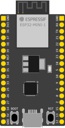
Pin Configuration and Descriptions
The ESP32-DevKitM-1 features a 20-pin layout. Below is the pin configuration:
| Pin Name | Type | Description |
|---|---|---|
| GND | Power | Ground connection |
| 3V3 | Power | 3.3V power output |
| EN | Input | Enable pin (active high) |
| IO0 | GPIO/Boot Mode | GPIO0, also used to enter bootloader mode |
| IO1 | GPIO/UART TX | GPIO1, UART TX for serial communication |
| IO3 | GPIO/UART RX | GPIO3, UART RX for serial communication |
| IO4 | GPIO | General-purpose input/output pin |
| IO5 | GPIO | General-purpose input/output pin |
| IO12 | GPIO/ADC | GPIO12, can also function as an ADC input |
| IO13 | GPIO/ADC | GPIO13, can also function as an ADC input |
| IO14 | GPIO/PWM | GPIO14, supports PWM output |
| IO15 | GPIO/PWM | GPIO15, supports PWM output |
| IO16 | GPIO | General-purpose input/output pin |
| IO17 | GPIO | General-purpose input/output pin |
| IO18 | GPIO/SPI CLK | GPIO18, SPI clock line |
| IO19 | GPIO/SPI MISO | GPIO19, SPI MISO line |
| IO21 | GPIO/I2C SDA | GPIO21, I2C data line |
| IO22 | GPIO/I2C SCL | GPIO22, I2C clock line |
| IO23 | GPIO/SPI MOSI | GPIO23, SPI MOSI line |
| VIN | Power | Input voltage (5V) for powering the board |
Usage Instructions
How to Use the ESP32-DevKitM-1 in a Circuit
Powering the Board:
- Connect the board to a computer or USB power source using a micro-USB cable.
- Alternatively, supply 5V to the VIN pin for external power.
Programming the Board:
- Install the Arduino IDE or Espressif's ESP-IDF development framework.
- Add the ESP32 board support package to the Arduino IDE via the Boards Manager.
- Select "ESP32 Dev Module" as the board type in the IDE.
Connecting Peripherals:
- Use the GPIO pins to connect sensors, actuators, or other peripherals.
- Ensure that the voltage levels of connected devices are compatible with the 3.3V logic of the ESP32.
Uploading Code:
- Write your program in the Arduino IDE or ESP-IDF.
- Connect the board to your computer via USB and select the appropriate COM port.
- Press the "Upload" button in the IDE to flash the code to the board.
Important Considerations and Best Practices
- Voltage Levels: The GPIO pins operate at 3.3V. Avoid connecting 5V signals directly to the pins to prevent damage.
- Boot Mode: To enter bootloader mode, hold down the IO0 button while pressing the EN button.
- Power Supply: Use a stable power source to avoid unexpected resets or performance issues.
- Antenna Placement: Ensure that the onboard antenna has sufficient clearance from metal objects to maintain optimal wireless performance.
Example Code for Arduino UNO Integration
Below is an example of using the ESP32-DevKitM-1 to control an LED via Wi-Fi:
#include <WiFi.h>

// Replace with your network credentials
const char* ssid = "Your_SSID";
const char* password = "Your_PASSWORD";

void setup() {
  Serial.begin(115200); // Initialize serial communication
  pinMode(2, OUTPUT);   // Set GPIO2 as an output pin (connected to an LED)

  // Connect to Wi-Fi
  Serial.print("Connecting to Wi-Fi");
  WiFi.begin(ssid, password);
  while (WiFi.status() != WL_CONNECTED) {
    delay(500);
    Serial.print(".");
  }
  Serial.println("\nWi-Fi connected!");
}

void loop() {
  digitalWrite(2, HIGH); // Turn the LED on
  delay(1000);           // Wait for 1 second
  digitalWrite(2, LOW);  // Turn the LED off
  delay(1000);           // Wait for 1 second
}
Troubleshooting and FAQs
Common Issues and Solutions
The board is not detected by the computer:
- Ensure the USB cable is functional and supports data transfer.
- Install the required USB-to-serial driver for the ESP32.
Code upload fails:
- Check that the correct COM port is selected in the IDE.
- Hold down the IO0 button while pressing the EN button to enter bootloader mode.
Wi-Fi connection issues:
- Verify the SSID and password in your code.
- Ensure the Wi-Fi network is within range and not overloaded.
GPIO pin not working as expected:
- Confirm that the pin is not being used for another function (e.g., boot mode).
- Check for short circuits or incorrect wiring.
FAQs
Can the ESP32-DevKitM-1 operate on battery power? Yes, you can power the board using a 3.7V LiPo battery connected to the 3V3 pin, but ensure proper regulation.
What is the maximum current output of the GPIO pins? Each GPIO pin can source or sink up to 12 mA safely.
Is the ESP32-DevKitM-1 compatible with Arduino libraries? Yes, most Arduino libraries are compatible with the ESP32, but some may require modifications.
This concludes the documentation for the ESP32-DevKitM-1. For further details, refer to the official Espressif documentation.