How to Use ESP32 Mini: Examples, Pinouts, and Specs
Introduction
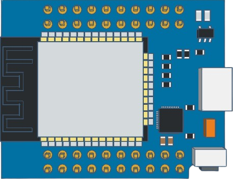
The ESP32 Mini is a compact and versatile microcontroller module that integrates Wi-Fi and Bluetooth connectivity, making it an ideal choice for Internet of Things (IoT) projects and wireless applications. With its dual-core processor and ample GPIO pins, the ESP32 Mini is capable of handling complex tasks and can be used in a variety of applications, including smart home devices, wearable electronics, and sensor networks.
Explore Projects Built with ESP32 Mini


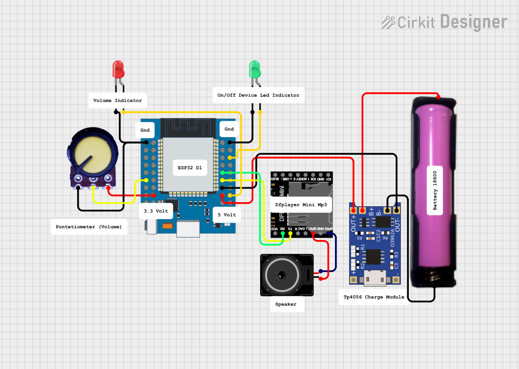

Explore Projects Built with ESP32 Mini
Technical Specifications
Key Technical Details
- Processor: Tensilica Xtensa® Dual-Core 32-bit LX6 microprocessor
- Operating Voltage: 3.3V
- Input Voltage (recommended): 5V
- Digital I/O Pins: 34 (GPIOs)
- Analog Input Pins: 12-bit SAR ADC up to 18 channels
- Analog Output Pins: 2 (8-bit DAC)
- Wi-Fi: 802.11 b/g/n (802.11n up to 150 Mbps)
- Bluetooth: v4.2 BR/EDR and BLE specification
- RAM: 520 KB SRAM
- Flash Memory: 4 MB
- Clock Speed: Up to 240 MHz
- Operating Temperature: -40°C to +125°C
Pin Configuration and Descriptions
| Pin Number | Function | Description |
|---|---|---|
| 1 | GND | Ground |
| 2 | 3V3 | 3.3V power supply |
| 3 | EN | Chip enable. Active high. |
| 4 | 36 (VP) | GPIO36, ADC1_CH0, Sensor VP |
| 5 | 39 (VN) | GPIO39, ADC1_CH3, Sensor VN |
| 6 | 34 | GPIO34, ADC1_CH6 (input only) |
| 7 | 35 | GPIO35, ADC1_CH7 (input only) |
| 8 | 32 | GPIO32, ADC1_CH4, XTAL_32K_P (input only) |
| 9 | 33 | GPIO33, ADC1_CH5, XTAL_32K_N (input only) |
| 10 | 25 | GPIO25, DAC_1 |
| 11 | 26 | GPIO26, DAC_2 |
| 12 | 27 | GPIO27, ADC2_CH7 |
| 13 | 14 | GPIO14, ADC2_CH6, TOUCH6, HSPI_CLK |
| 14 | 12 | GPIO12, ADC2_CH5, TOUCH5, HSPI_MISO, MTDI |
| 15 | GND | Ground |
| 16 | 23 | GPIO23, VSPID |
| 17 | 22 | GPIO22, VSPIWP, U0RTS |
| 18 | 1 | GPIO1, U0TXD |
| 19 | 3 | GPIO3, U0RXD |
| 20 | 21 | GPIO21, VSPIHD, U0CTS |
| 21 | GND | Ground |
| 22 | 19 | GPIO19, VSPIQ, U0CTS |
| 23 | 18 | GPIO18, VSPICLK |
| 24 | 5 | GPIO5, VSPICS0 |
| 25 | 17 | GPIO17, U2TXD |
| 26 | 16 | GPIO16, U2RXD |
| 27 | GND | Ground |
| 28 | 4 | GPIO4, ADC2_CH0, TOUCH0 |
| 29 | 0 | GPIO0, ADC2_CH1, TOUCH1, BOOT |
| 30 | 2 | GPIO2, ADC2_CH2, TOUCH2, HSPIWP, U1TXD |
| 31 | 15 | GPIO15, ADC2_CH3, TOUCH3, MTDO, HSPICS0, U1RXD |
| 32 | 13 | GPIO13, ADC2_CH4, TOUCH4, HSPIQ, U1CTS |
| 33 | GND | Ground |
| 34 | 23 | GPIO23, VSPID |
| 35 | 22 | GPIO22, VSPIWP, U0RTS |
Usage Instructions
Integrating ESP32 Mini into a Circuit
- Power Supply: Connect a 5V power source to the VIN pin and ground to one of the GND pins. Alternatively, you can supply 3.3V directly to the 3V3 pin.
- Boot Mode: To upload code, ensure GPIO0 is connected to GND during power-up or reset to enter bootloader mode.
- Serial Communication: Use GPIO1 (TX) and GPIO3 (RX) for serial communication with a computer or other devices.
- Wi-Fi and Bluetooth: Utilize the built-in Wi-Fi and Bluetooth for wireless communication. Ensure proper antenna design or connection for optimal performance.
- GPIO Pins: Connect sensors, actuators, or other peripherals to the GPIO pins as required by your project. Be mindful of the input/output capabilities and voltage levels of each pin.
Best Practices
- Use a voltage regulator to ensure a stable 3.3V supply if powering the ESP32 Mini with more than 3.3V.
- Avoid drawing more than 12 mA from any GPIO pin to prevent damage to the device.
- When using ADC pins, be aware that the input voltage range is 0 to 3.3V.
- For high-frequency signals or applications requiring precise timing, use the pins marked as HSPI (High-Speed SPI).
Troubleshooting and FAQs
Common Issues
- Failure to Connect to Wi-Fi: Ensure the Wi-Fi credentials are correct and the ESP32 Mini is within range of the router.
- Unexpected Resets: This can be caused by an inadequate power supply. Make sure the power source can deliver sufficient current.
- GPIO Pin Not Working: Check if the pin is configured correctly in the code and that there are no shorts or open circuits in your connections.
Solutions and Tips
- Improving Wi-Fi Range: Use an external antenna or ensure the onboard antenna is not obstructed.
- Code Upload Issues: If you're having trouble uploading code, ensure GPIO0 is grounded and the ESP32 Mini is in bootloader mode.
- Serial Communication Errors: Verify the baud rate and other serial settings match between the ESP32 Mini and the device it's communicating with.
Example Code for Arduino UNO
#include <WiFi.h>

// Replace with your network credentials
const char* ssid = "your_SSID";
const char* password = "your_PASSWORD";

void setup() {
  Serial.begin(115200);

  // Connect to Wi-Fi
  WiFi.begin(ssid, password);
  while (WiFi.status() != WL_CONNECTED) {
    delay(500);
    Serial.println("Connecting to WiFi...");
  }

  Serial.println("Connected to WiFi");
}

void loop() {
  // Your code here
}
Note: This example demonstrates how to connect the ESP32 Mini to a Wi-Fi network. Replace your_SSID and your_PASSWORD with your actual Wi-Fi credentials. The Serial.begin(115200); line initializes serial communication at a baud rate of 115200, which is commonly used for ESP32 modules.
For further assistance or questions, refer to the manufacturer's datasheet or contact technical support.