How to Use LCD ekran: Examples, Pinouts, and Specs
Introduction
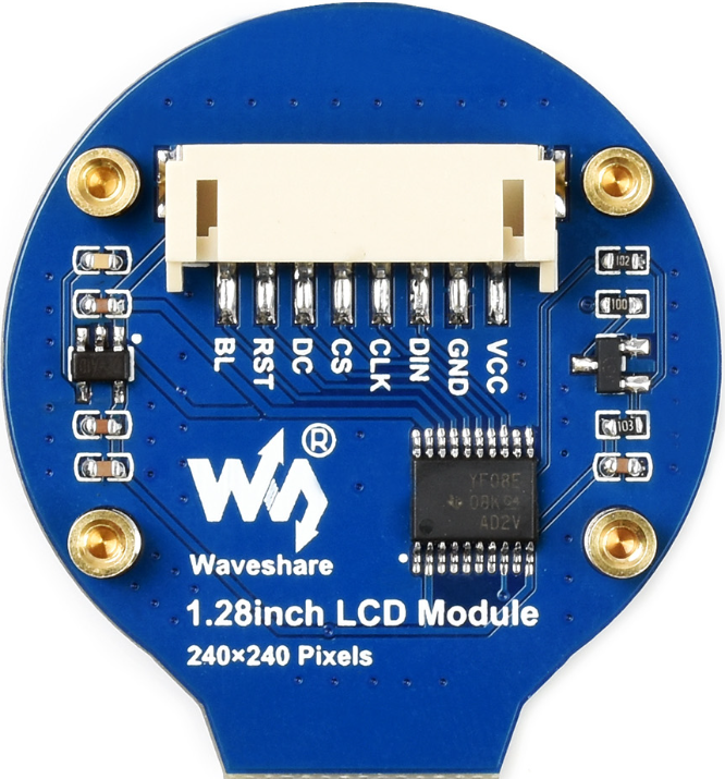
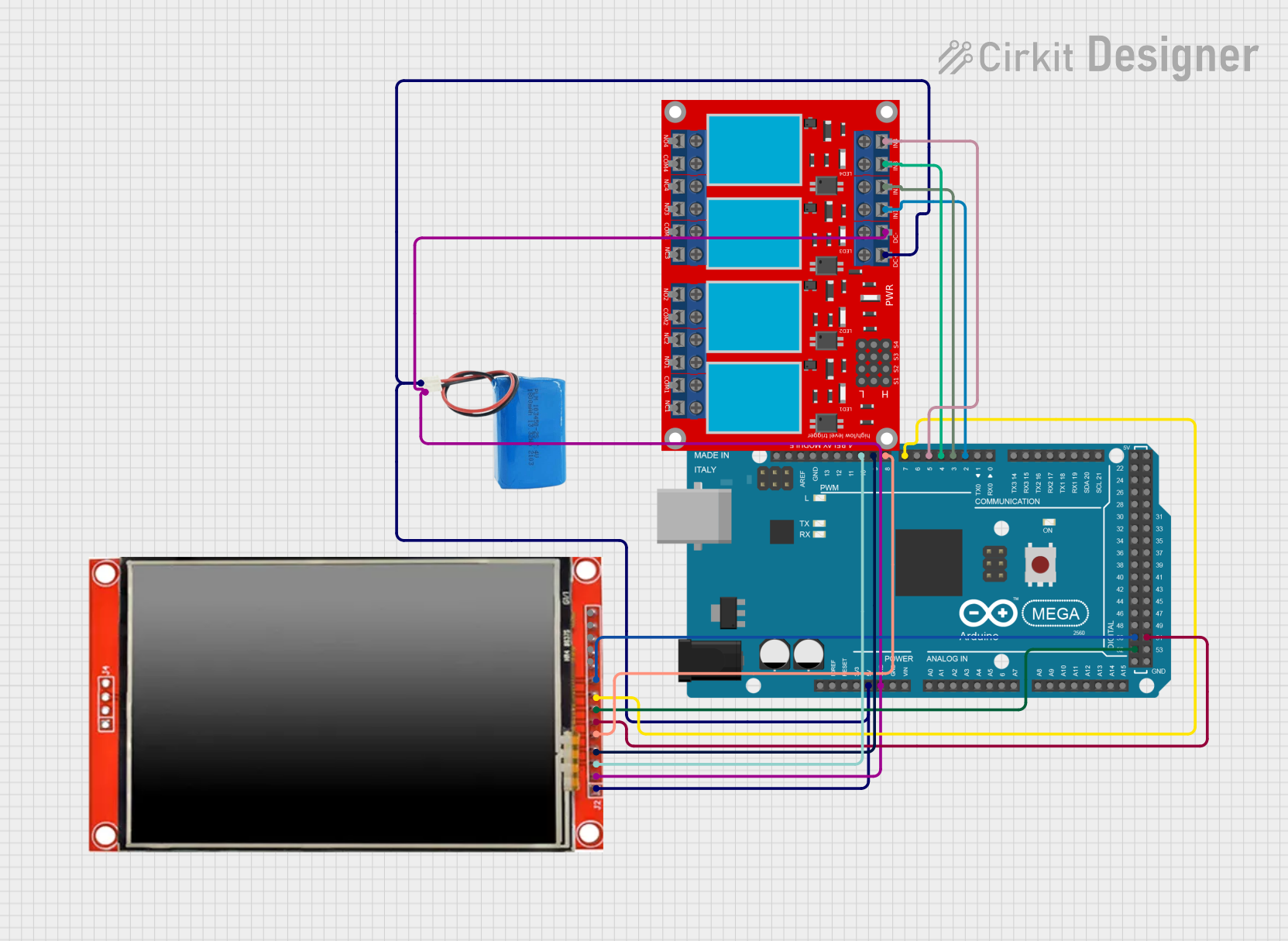
The Waveshare LCD (Part ID: LCD) is a Liquid Crystal Display (LCD) screen designed for displaying text, images, and graphical content in a wide range of electronic applications. Utilizing liquid crystal technology, this display offers high-quality visuals with low power consumption, making it an ideal choice for embedded systems, IoT devices, and consumer electronics.
Explore Projects Built with LCD ekran
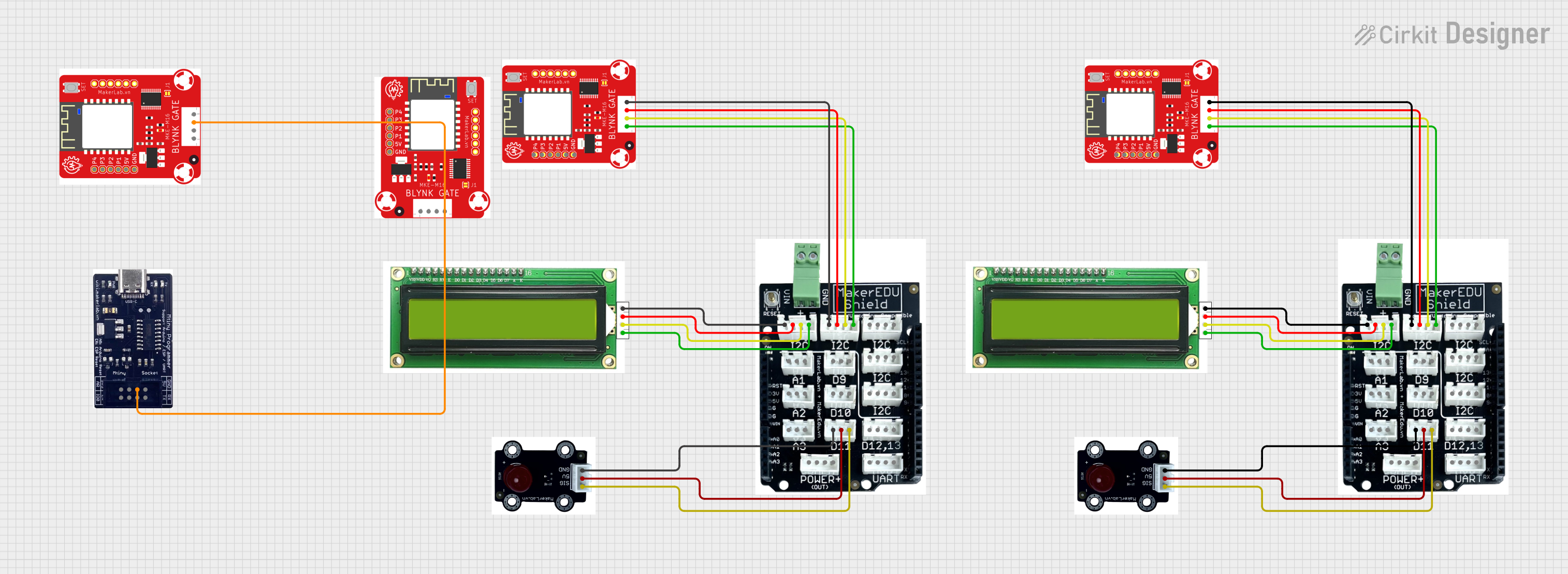
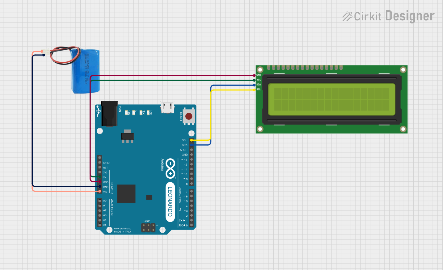
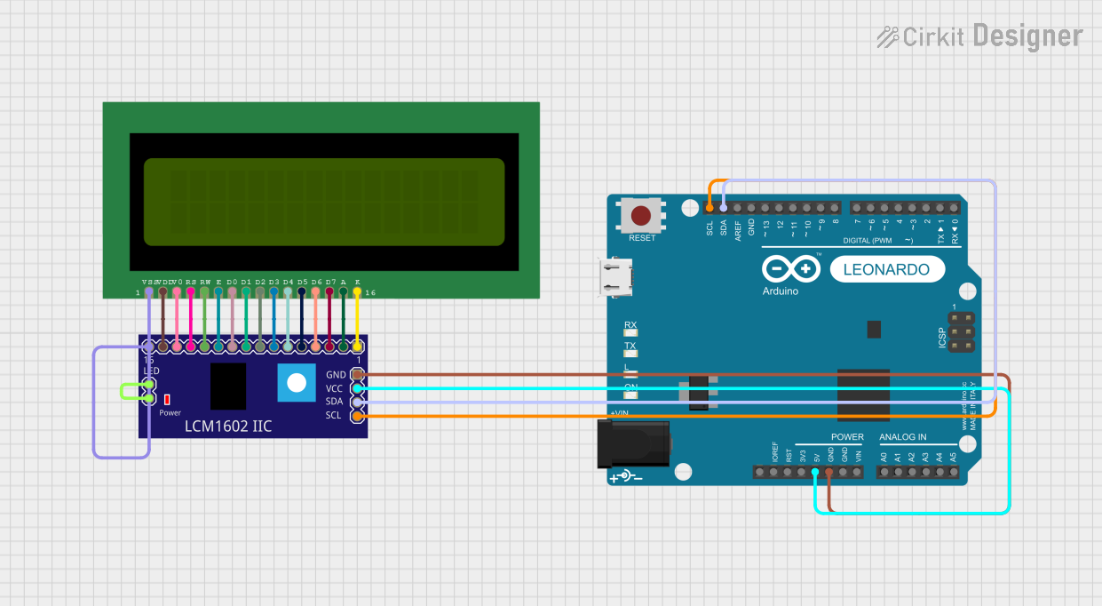
Explore Projects Built with LCD ekran
Common Applications and Use Cases
- Embedded systems and microcontroller projects
- IoT devices with user interfaces
- Consumer electronics such as calculators, clocks, and appliances
- Educational and prototyping purposes
- Industrial control panels and instrumentation
Technical Specifications
The following table outlines the key technical details of the Waveshare LCD:
| Parameter | Value |
|---|---|
| Manufacturer | Waveshare |
| Part ID | LCD |
| Display Type | Liquid Crystal Display (LCD) |
| Operating Voltage | 3.3V or 5V |
| Power Consumption | Low |
| Interface Type | Parallel or Serial (I2C/SPI) |
| Resolution | Varies (e.g., 16x2, 20x4) |
| Backlight | LED (adjustable brightness) |
| Operating Temperature | -20°C to 70°C |
Pin Configuration and Descriptions
The pin configuration may vary depending on the specific model of the LCD. Below is a typical pinout for a 16x2 LCD module with a parallel interface:
| Pin | Name | Description |
|---|---|---|
| 1 | VSS | Ground (0V) connection |
| 2 | VDD | Power supply (3.3V or 5V) |
| 3 | VO | Contrast adjustment (connect to a potentiometer for contrast control) |
| 4 | RS | Register Select (0: Command, 1: Data) |
| 5 | RW | Read/Write (0: Write, 1: Read) |
| 6 | E | Enable signal (triggers data read/write) |
| 7-14 | D0-D7 | Data pins (used for 8-bit or 4-bit communication) |
| 15 | LED+ | Backlight anode (connect to power through a resistor for brightness control) |
| 16 | LED- | Backlight cathode (connect to ground) |
For I2C-based LCD modules, the pinout is typically reduced to 4 pins:
| Pin | Name | Description |
|---|---|---|
| 1 | GND | Ground (0V) connection |
| 2 | VCC | Power supply (3.3V or 5V) |
| 3 | SDA | Serial Data Line (I2C communication) |
| 4 | SCL | Serial Clock Line (I2C communication) |
Usage Instructions
How to Use the Component in a Circuit
- Power Supply: Connect the VDD pin to a 3.3V or 5V power source and the VSS pin to ground.
- Contrast Adjustment: Use a 10kΩ potentiometer connected to the VO pin to adjust the display contrast.
- Communication Mode:
- For parallel communication, connect the RS, RW, E, and data pins (D0-D7) to the microcontroller.
- For I2C communication, connect the SDA and SCL pins to the corresponding I2C pins on the microcontroller.
- Backlight: Connect the LED+ pin to power through a current-limiting resistor and the LED- pin to ground.
- Initialization: Initialize the LCD in your code by sending the appropriate commands to configure the display mode (e.g., 4-bit or 8-bit mode).
Important Considerations and Best Practices
- Ensure the power supply voltage matches the LCD's operating voltage (3.3V or 5V).
- Use a current-limiting resistor for the backlight to prevent damage.
- For I2C modules, ensure the correct I2C address is used in your code (commonly 0x27 or 0x3F).
- Avoid excessive contrast settings, as this may reduce the display's lifespan.
Example Code for Arduino UNO
Below is an example of how to use a 16x2 I2C LCD with an Arduino UNO:
#include <Wire.h>
#include <LiquidCrystal_I2C.h>

// Initialize the LCD with I2C address 0x27 and dimensions 16x2
LiquidCrystal_I2C lcd(0x27, 16, 2);

void setup() {
  lcd.init(); // Initialize the LCD
  lcd.backlight(); // Turn on the backlight
  lcd.setCursor(0, 0); // Set cursor to the first row, first column
  lcd.print("Hello, World!"); // Display text on the LCD
}

void loop() {
  // No actions in the loop for this example
}
Troubleshooting and FAQs
Common Issues and Solutions
No Display on the Screen:
- Ensure the power supply is connected and providing the correct voltage.
- Check the contrast adjustment; turn the potentiometer to see if the text appears.
- Verify the connections between the LCD and the microcontroller.
Backlight Not Working:
- Check the LED+ and LED- connections.
- Ensure a current-limiting resistor is used and is of the correct value.
Incorrect or Garbled Characters:
- Verify the communication mode (4-bit, 8-bit, or I2C) and ensure the code matches the configuration.
- Check for loose or incorrect wiring.
I2C LCD Not Responding:
- Confirm the I2C address of the LCD module (use an I2C scanner sketch if necessary).
- Ensure the SDA and SCL lines are connected to the correct pins on the microcontroller.
FAQs
Q: Can I use the LCD with a 3.3V microcontroller?
A: Yes, the LCD is compatible with both 3.3V and 5V systems. Ensure the power supply and logic levels match.
Q: How do I find the I2C address of my LCD?
A: Use an I2C scanner sketch to detect the address. Common addresses are 0x27 and 0x3F.
Q: Can I control the backlight brightness?
A: Yes, you can use a PWM signal or a variable resistor to adjust the backlight brightness.
Q: Is the LCD compatible with other microcontrollers?
A: Yes, the LCD can be used with various microcontrollers, including Arduino, Raspberry Pi, and STM32, as long as the communication protocol is supported.