Cirkit Designer Logo
Cirkit Designer
Your all-in-one circuit design IDE
Home / 
Component Documentation

How to Use Emergency STOP: Examples, Pinouts, and Specs

Image of Emergency STOP
Cirkit Designer LogoDesign with Emergency STOP in Cirkit Designer

Introduction

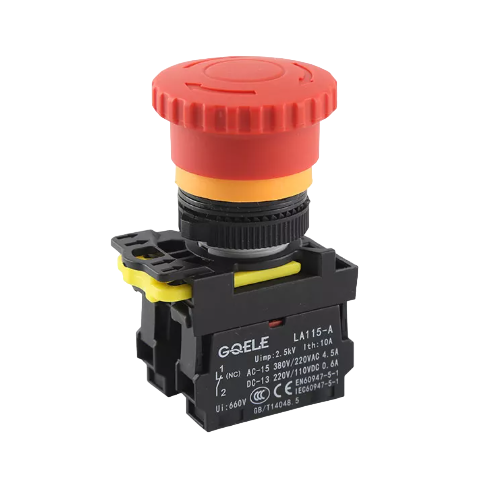
An Emergency Stop (E-STOP) button is a critical safety device designed to halt the operation of machinery and processes in the event of an emergency. It is a fail-safe control mechanism that can be activated with a simple push, providing an immediate response to potential hazards. E-STOP buttons are commonly found in industrial settings, on control panels, and within electronic systems where human safety or equipment protection is paramount.

Explore Projects Built with Emergency STOP

Use Cirkit Designer to design, explore, and prototype these projects online. Some projects support real-time simulation. Click "Open Project" to start designing instantly!
Arduino Nano Controlled Relay System with Safety Interlocks
Image of HYD: A project utilizing Emergency STOP in a practical application
This circuit includes an Arduino Nano microcontroller interfaced with multiple pushbuttons, limit switches, an emergency stop, a 2-channel relay module, and a 1-channel relay module. The Arduino controls the relay modules based on inputs from the pushbuttons and limit switches, which likely serve as user interfaces and position or safety sensors. The circuit is powered by a 5V power supply unit (PSU), which is connected to an AC supply, and the emergency stop is configured to potentially interrupt the circuit for safety purposes.
Cirkit Designer LogoOpen Project in Cirkit Designer
Battery-Powered Emergency Alert System with NUCLEO-F072RB, SIM800L, and GPS NEO 6M
Image of women safety: A project utilizing Emergency STOP in a practical application
This circuit is an emergency alert system that uses a NUCLEO-F072RB microcontroller to send SMS alerts and make calls via a SIM800L GSM module, while obtaining location data from a GPS NEO 6M module. The system is powered by a Li-ion battery and includes a TP4056 module for battery charging and protection, with a rocker switch to control power to the microcontroller.
Cirkit Designer LogoOpen Project in Cirkit Designer
ESP32-Based Sensor Monitoring System with OLED Display and E-Stop
Image of MVP_design: A project utilizing Emergency STOP in a practical application
This circuit features an ESP32 microcontroller that interfaces with a variety of sensors and output devices. It is powered by a Lipo battery through a buck converter, ensuring a stable voltage supply. The ESP32 collects data from a DHT11 temperature and humidity sensor and a vibration sensor, controls a buzzer, and displays information on an OLED screen. An emergency stop (E Stop) is connected for safety purposes, allowing the system to be quickly deactivated.
Cirkit Designer LogoOpen Project in Cirkit Designer
Arduino Mega 2560-Based Safety Monitoring and Control System with Temperature Sensor and Relay Module
Image of conveyor_V_1: A project utilizing Emergency STOP in a practical application
This circuit is a safety and control system using an Arduino Mega 2560, which monitors various switches and a DHT11 sensor to control an 8-channel relay module. The system includes emergency stop buttons, pushbuttons, and a 3-position switch to manage safety conditions and activate relays based on temperature and switch inputs.
Cirkit Designer LogoOpen Project in Cirkit Designer

Explore Projects Built with Emergency STOP

Use Cirkit Designer to design, explore, and prototype these projects online. Some projects support real-time simulation. Click "Open Project" to start designing instantly!
Image of HYD: A project utilizing Emergency STOP in a practical application
Arduino Nano Controlled Relay System with Safety Interlocks
This circuit includes an Arduino Nano microcontroller interfaced with multiple pushbuttons, limit switches, an emergency stop, a 2-channel relay module, and a 1-channel relay module. The Arduino controls the relay modules based on inputs from the pushbuttons and limit switches, which likely serve as user interfaces and position or safety sensors. The circuit is powered by a 5V power supply unit (PSU), which is connected to an AC supply, and the emergency stop is configured to potentially interrupt the circuit for safety purposes.
Cirkit Designer LogoOpen Project in Cirkit Designer
Image of women safety: A project utilizing Emergency STOP in a practical application
Battery-Powered Emergency Alert System with NUCLEO-F072RB, SIM800L, and GPS NEO 6M
This circuit is an emergency alert system that uses a NUCLEO-F072RB microcontroller to send SMS alerts and make calls via a SIM800L GSM module, while obtaining location data from a GPS NEO 6M module. The system is powered by a Li-ion battery and includes a TP4056 module for battery charging and protection, with a rocker switch to control power to the microcontroller.
Cirkit Designer LogoOpen Project in Cirkit Designer
Image of MVP_design: A project utilizing Emergency STOP in a practical application
ESP32-Based Sensor Monitoring System with OLED Display and E-Stop
This circuit features an ESP32 microcontroller that interfaces with a variety of sensors and output devices. It is powered by a Lipo battery through a buck converter, ensuring a stable voltage supply. The ESP32 collects data from a DHT11 temperature and humidity sensor and a vibration sensor, controls a buzzer, and displays information on an OLED screen. An emergency stop (E Stop) is connected for safety purposes, allowing the system to be quickly deactivated.
Cirkit Designer LogoOpen Project in Cirkit Designer
Image of conveyor_V_1: A project utilizing Emergency STOP in a practical application
Arduino Mega 2560-Based Safety Monitoring and Control System with Temperature Sensor and Relay Module
This circuit is a safety and control system using an Arduino Mega 2560, which monitors various switches and a DHT11 sensor to control an 8-channel relay module. The system includes emergency stop buttons, pushbuttons, and a 3-position switch to manage safety conditions and activate relays based on temperature and switch inputs.
Cirkit Designer LogoOpen Project in Cirkit Designer

Common Applications and Use Cases

  • Industrial machinery
  • Robotic systems
  • Conveyor belts
  • Automated production lines
  • CNC machines
  • Laboratory equipment

Technical Specifications

Key Technical Details

  • Voltage Rating: Typically 24V to 240V AC/DC
  • Current Rating: Up to 10A (varies by model)
  • Contact Configuration: Normally closed (NC), opens upon activation
  • Durability: Rated for a high number of cycles (mechanical and electrical)

Pin Configuration and Descriptions

Pin Number Description Notes
1 Common (COM) Connect to power supply
2 Normally Closed (NC) Connect to the control circuit
3 Normally Open (NO) Unused in most E-STOP circuits

Usage Instructions

How to Use the Component in a Circuit

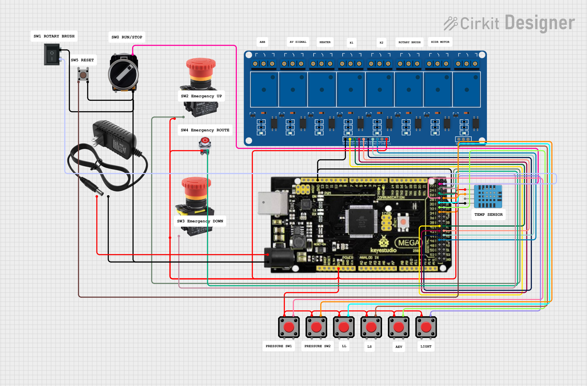
  1. Wiring the E-STOP Button:

    • Connect the COM pin to the positive terminal of the power supply.
    • Connect the NC pin to the control circuit that needs to be interrupted during an emergency.
  2. Mounting the E-STOP Button:

    • Place the E-STOP button in an accessible location.
    • Ensure it is clearly marked and unobstructed.
  3. Testing the E-STOP Button:

    • Perform regular tests to ensure functionality.
    • Check for mechanical freedom and reliable contact break.

Important Considerations and Best Practices

  • Visibility: The E-STOP button should be highly visible and marked with a red color.
  • Accessibility: It must be easily accessible and within reach of the operator at all times.
  • Wiring: Use appropriate gauge wire to handle the expected current.
  • Compliance: Ensure the E-STOP button meets relevant safety standards and regulations.

Troubleshooting and FAQs

Common Issues Users Might Face

  • E-STOP Button Does Not Respond:

    • Check the wiring connections for any loose or broken wires.
    • Verify the power supply is functioning and delivering the correct voltage.
    • Inspect the button for any physical damage or obstructions.
  • False Triggering:

    • Ensure there is no vibration or mechanical stress causing accidental activation.
    • Check for any electrical interference that may cause unintended operation.

Solutions and Tips for Troubleshooting

  • Regularly inspect and maintain the E-STOP button for reliable performance.
  • If the button is unresponsive, consider replacing it as it is a critical safety component.
  • For false triggering, isolate the button from sources of interference or mechanical stress.

FAQs

Q: Can I use the NO pin for an E-STOP function? A: No, the E-STOP function should always use the NC contact to ensure the circuit is broken in an emergency.

Q: How often should I test the E-STOP button? A: It is recommended to test the E-STOP button before each use of the machinery or at least once a month.

Q: What should I do if the E-STOP button is accidentally activated? A: Reset the system according to the manufacturer's instructions, ensuring that it is safe to resume operation.

Example Code for Arduino UNO

// Define the E-STOP button pin
const int estopPin = 2;

void setup() {
  // Set the E-STOP pin as an input with an internal pull-up resistor
  pinMode(estopPin, INPUT_PULLUP);
  // Initialize serial communication for debugging
  Serial.begin(9600);
}

void loop() {
  // Check the E-STOP button state
  int estopState = digitalRead(estopPin);
  
  // If the button is pressed (circuit is open), halt the system
  if (estopState == HIGH) {
    // Implement emergency stop procedures
    Serial.println("EMERGENCY STOP ACTIVATED");
    // Add code here to safely shut down any connected systems
    // ...
  }
  // Otherwise, continue normal operation
  else {
    // Normal operation code
    // ...
  }
}

Note: In this example, the Arduino's internal pull-up resistor is used, which means the E-STOP button is connected between the pin and ground. The circuit is normally closed, and when the E-STOP is pressed, the circuit opens, reading HIGH on the input pin.