Cirkit Designer Logo
Cirkit Designer
Your all-in-one circuit design IDE
Home / 
Component Documentation

How to Use Si4703: Examples, Pinouts, and Specs

Image of Si4703
Cirkit Designer LogoDesign with Si4703 in Cirkit Designer

Introduction

The Si4703 by JESSINE is a low-power FM radio receiver IC designed for portable and compact applications. It features a built-in digital signal processing (DSP) engine that ensures high-quality audio reception. The chip supports various audio formats and includes an integrated antenna switch, making it a versatile choice for FM radio integration. Its I2C interface allows for easy control and communication with microcontrollers, making it ideal for modern electronic devices.

Explore Projects Built with Si4703

Use Cirkit Designer to design, explore, and prototype these projects online. Some projects support real-time simulation. Click "Open Project" to start designing instantly!
Satellite-Based Timing and Navigation System with SDR and Atomic Clock Synchronization
Image of GPS 시스템 측정 구성도_Confirm: A project utilizing Si4703 in a practical application
This circuit appears to be a complex system involving power supply management, GPS and timing synchronization, and data communication. It includes a SI-TEX G1 Satellite Compass for GPS data, an XHTF1021 Atomic Rubidium Clock for precise timing, and Ettus USRP B200 units for software-defined radio communication. Power is supplied through various SMPS units and distributed via terminal blocks and DC jacks. Data communication is facilitated by Beelink MINI S12 N95 computers, RS232 splitters, and a 1000BASE-T Media Converter for network connectivity. RF Directional Couplers are used to interface antennas with the USRP units, and the entire system is likely contained within cases for protection and organization.
Cirkit Designer LogoOpen Project in Cirkit Designer
Cellular-Enabled IoT Device with Real-Time Clock and Power Management
Image of LRCM PHASE 2 BASIC: A project utilizing Si4703 in a practical application
This circuit features a LilyGo-SIM7000G module for cellular communication and GPS functionality, interfaced with an RTC DS3231 for real-time clock capabilities. It includes voltage sensing through two voltage sensor modules, and uses an 8-channel opto-coupler for isolating different parts of the circuit. Power management is handled by a buck converter connected to a DC power source and batteries, with a fuse for protection and a rocker switch for on/off control. Additionally, there's an LED for indication purposes.
Cirkit Designer LogoOpen Project in Cirkit Designer
Cellular-Connected ESP32-CAM with Real-Time Clock and Isolated Control
Image of LRCM PHASE 2 PRO: A project utilizing Si4703 in a practical application
This circuit integrates a LilyGo-SIM7000G module with an RTC DS3231 for timekeeping, interfaced via I2C (SCL and SDA lines). An 8-Channel OPTO-COUPLER is used to isolate and interface external signals with the LilyGo-SIM7000G's GPIOs. Power is managed by a Buck converter, which steps down voltage from a DC Power Source to supply the ESP32-CAM and LilyGo-SIM7000G modules, as well as the OPTO-COUPLER.
Cirkit Designer LogoOpen Project in Cirkit Designer
Battery-Powered Emergency Alert System with NUCLEO-F072RB, SIM800L, and GPS NEO 6M
Image of women safety: A project utilizing Si4703 in a practical application
This circuit is an emergency alert system that uses a NUCLEO-F072RB microcontroller to send SMS alerts and make calls via a SIM800L GSM module, while obtaining location data from a GPS NEO 6M module. The system is powered by a Li-ion battery and includes a TP4056 module for battery charging and protection, with a rocker switch to control power to the microcontroller.
Cirkit Designer LogoOpen Project in Cirkit Designer

Explore Projects Built with Si4703

Use Cirkit Designer to design, explore, and prototype these projects online. Some projects support real-time simulation. Click "Open Project" to start designing instantly!
Image of GPS 시스템 측정 구성도_Confirm: A project utilizing Si4703 in a practical application
Satellite-Based Timing and Navigation System with SDR and Atomic Clock Synchronization
This circuit appears to be a complex system involving power supply management, GPS and timing synchronization, and data communication. It includes a SI-TEX G1 Satellite Compass for GPS data, an XHTF1021 Atomic Rubidium Clock for precise timing, and Ettus USRP B200 units for software-defined radio communication. Power is supplied through various SMPS units and distributed via terminal blocks and DC jacks. Data communication is facilitated by Beelink MINI S12 N95 computers, RS232 splitters, and a 1000BASE-T Media Converter for network connectivity. RF Directional Couplers are used to interface antennas with the USRP units, and the entire system is likely contained within cases for protection and organization.
Cirkit Designer LogoOpen Project in Cirkit Designer
Image of LRCM PHASE 2 BASIC: A project utilizing Si4703 in a practical application
Cellular-Enabled IoT Device with Real-Time Clock and Power Management
This circuit features a LilyGo-SIM7000G module for cellular communication and GPS functionality, interfaced with an RTC DS3231 for real-time clock capabilities. It includes voltage sensing through two voltage sensor modules, and uses an 8-channel opto-coupler for isolating different parts of the circuit. Power management is handled by a buck converter connected to a DC power source and batteries, with a fuse for protection and a rocker switch for on/off control. Additionally, there's an LED for indication purposes.
Cirkit Designer LogoOpen Project in Cirkit Designer
Image of LRCM PHASE 2 PRO: A project utilizing Si4703 in a practical application
Cellular-Connected ESP32-CAM with Real-Time Clock and Isolated Control
This circuit integrates a LilyGo-SIM7000G module with an RTC DS3231 for timekeeping, interfaced via I2C (SCL and SDA lines). An 8-Channel OPTO-COUPLER is used to isolate and interface external signals with the LilyGo-SIM7000G's GPIOs. Power is managed by a Buck converter, which steps down voltage from a DC Power Source to supply the ESP32-CAM and LilyGo-SIM7000G modules, as well as the OPTO-COUPLER.
Cirkit Designer LogoOpen Project in Cirkit Designer
Image of women safety: A project utilizing Si4703 in a practical application
Battery-Powered Emergency Alert System with NUCLEO-F072RB, SIM800L, and GPS NEO 6M
This circuit is an emergency alert system that uses a NUCLEO-F072RB microcontroller to send SMS alerts and make calls via a SIM800L GSM module, while obtaining location data from a GPS NEO 6M module. The system is powered by a Li-ion battery and includes a TP4056 module for battery charging and protection, with a rocker switch to control power to the microcontroller.
Cirkit Designer LogoOpen Project in Cirkit Designer

Common Applications

  • Portable FM radios
  • MP3 players with FM functionality
  • Wearable devices with radio features
  • Automotive infotainment systems
  • Home audio systems

Technical Specifications

Key Technical Details

Parameter Value
Operating Voltage 2.7V to 5.5V
Supply Current 19 mA (typical)
Frequency Range 76 MHz to 108 MHz
Audio Output Analog stereo
Interface I2C
Sensitivity -110 dBm
Antenna Input Impedance 50 Ω
Package Type 20-pin SSOP
Operating Temperature Range -20°C to +85°C

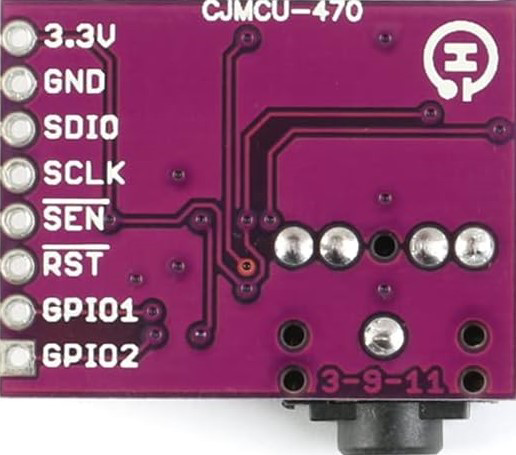
Pin Configuration and Descriptions

Pin Number Pin Name Description
1 GND Ground
2 VDD Power supply input (2.7V to 5.5V)
3 SDA I2C data line
4 SCL I2C clock line
5 RFGND RF ground for antenna
6 ANTENNA Antenna input
7 GPIO1 General-purpose I/O pin
8 GPIO2 General-purpose I/O pin
9 RST Reset pin (active low)
10 LOUT Left audio output
11 ROUT Right audio output
12-20 NC No connection

Usage Instructions

How to Use the Si4703 in a Circuit

  1. Power Supply: Connect the VDD pin to a regulated power supply (2.7V to 5.5V). Ensure proper decoupling capacitors are placed near the VDD pin to reduce noise.
  2. I2C Communication: Connect the SDA and SCL pins to the corresponding I2C pins of your microcontroller. Use pull-up resistors (typically 4.7 kΩ) on both lines.
  3. Antenna: Attach an external antenna to the ANTENNA pin for optimal FM signal reception. Ensure the antenna impedance matches the 50 Ω input impedance of the chip.
  4. Audio Output: Connect the LOUT and ROUT pins to an audio amplifier or headphones for stereo audio output.
  5. Reset: Use the RST pin to initialize the chip. Pull the pin low for at least 10 ms during startup.

Important Considerations

  • Antenna Placement: Place the antenna away from noisy components to avoid interference.
  • I2C Address: The default I2C address of the Si4703 is 0x10. Ensure no address conflicts with other devices on the I2C bus.
  • Bypass Capacitors: Use appropriate bypass capacitors (e.g., 0.1 µF) near the power supply pins to stabilize the voltage.
  • GPIO Pins: Configure GPIO1 and GPIO2 as needed for additional functionality, such as interrupts or status indicators.

Example Code for Arduino UNO

Below is an example of how to interface the Si4703 with an Arduino UNO to tune to an FM station:

#include <Wire.h> // Include the Wire library for I2C communication

#define SI4703_ADDRESS 0x10 // Default I2C address of the Si4703

void setup() {
  Wire.begin(); // Initialize I2C communication
  Serial.begin(9600); // Initialize serial communication for debugging

  // Reset the Si4703
  pinMode(2, OUTPUT); // Use pin 2 for the RST pin
  digitalWrite(2, LOW); // Pull RST low
  delay(10); // Wait for 10 ms
  digitalWrite(2, HIGH); // Release RST
  delay(100); // Wait for the chip to initialize

  // Initialize the Si4703
  Wire.beginTransmission(SI4703_ADDRESS);
  Wire.write(0x02); // Write to the POWERCFG register
  Wire.write(0x4001); // Enable the chip and set to FM mode
  Wire.endTransmission();
  delay(100);

  Serial.println("Si4703 initialized.");
}

void loop() {
  // Example: Tune to 101.1 MHz
  uint16_t frequency = 1011; // Frequency in 100 kHz steps (101.1 MHz = 1011)
  Wire.beginTransmission(SI4703_ADDRESS);
  Wire.write(0x03); // Write to the CHANNEL register
  Wire.write((frequency << 6) | 0x8000); // Set frequency and enable tuning
  Wire.endTransmission();
  delay(100);

  Serial.println("Tuned to 101.1 MHz.");
  while (1); // Stop the loop
}

Notes:

  • Ensure the RST pin is connected to a digital pin on the Arduino for proper initialization.
  • Modify the frequency variable in the code to tune to a different FM station.

Troubleshooting and FAQs

Common Issues

  1. No Audio Output:

    • Ensure the antenna is properly connected and positioned for optimal reception.
    • Verify that the audio output pins (LOUT and ROUT) are connected to an amplifier or headphones.
  2. I2C Communication Failure:

    • Check the pull-up resistors on the SDA and SCL lines.
    • Ensure the I2C address (0x10) matches the address in your code.
  3. Poor Signal Reception:

    • Use a longer or higher-quality antenna.
    • Avoid placing the Si4703 near high-frequency noise sources.
  4. Chip Not Responding:

    • Verify the RST pin is correctly toggled during initialization.
    • Check the power supply voltage and ensure it is within the specified range.

FAQs

Q: Can the Si4703 receive AM radio signals?
A: No, the Si4703 is designed specifically for FM radio reception.

Q: What is the maximum distance for FM signal reception?
A: The reception range depends on the antenna quality and environmental factors. Typically, it can receive signals from 10 to 50 miles in ideal conditions.

Q: Can I use the Si4703 with a 3.3V microcontroller?
A: Yes, the Si4703 operates within a voltage range of 2.7V to 5.5V, making it compatible with 3.3V systems.

Q: How do I improve audio quality?
A: Use a high-quality antenna and ensure proper grounding to minimize noise and interference.