Cirkit Designer Logo
Cirkit Designer
Your all-in-one circuit design IDE
Home / 
Component Documentation

How to Use XL 6009 Boost Module: Examples, Pinouts, and Specs

Image of XL 6009 Boost Module
Cirkit Designer LogoDesign with XL 6009 Boost Module in Cirkit Designer

Introduction

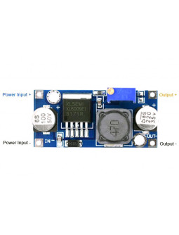
The XL6009 Boost Module is a high-efficiency DC-DC adjustable step-up (boost) converter designed to increase a lower input voltage to a higher output voltage. It is based on the XL6009 regulator chip and is capable of driving a load with higher voltage requirements. This module is commonly used in applications such as powering LED strips, motors, and other electronic devices that require a voltage higher than the available source.

Explore Projects Built with XL 6009 Boost Module

Use Cirkit Designer to design, explore, and prototype these projects online. Some projects support real-time simulation. Click "Open Project" to start designing instantly!
Battery-Powered Boost Converter with USB Type-C and BMS
Image of Weird Case: A project utilizing XL 6009 Boost Module in a practical application
This circuit is a power management and conversion system that includes a boost converter, battery management system (BMS), and various MOSFETs and passive components. It is designed to regulate and boost the voltage from a 2000mAh battery, providing stable power output through a USB Type C interface. The circuit also includes protection and switching mechanisms to ensure safe and efficient power delivery.
Cirkit Designer LogoOpen Project in Cirkit Designer
Battery-Powered Audio Playback and Amplification System
Image of recorder: A project utilizing XL 6009 Boost Module in a practical application
This circuit is designed to charge 18650 lithium-ion batteries using a TP4056 charger module, and then boost the voltage using an XL 6009 Boost Module. The boosted voltage is regulated by a 7805 voltage regulator to provide a stable 5V output, which powers an ISD1820 voice recording and playback module. The audio signal from the ISD1820 is then amplified by an LM386 audio amplifier module and output through a loudspeaker.
Cirkit Designer LogoOpen Project in Cirkit Designer
Voltage Regulation System with MT3608 Boost and LM2596 Buck Converters
Image of solar system router ups: A project utilizing XL 6009 Boost Module in a practical application
This circuit consists of two MT3608 boost converters and an LM2596 step-down module, each connected to separate 12V power supplies. The MT3608 modules are configured to step up the voltage from their respective power supplies, while the LM2596 module steps down the voltage from a 12V battery. Diodes are used to ensure correct current flow direction, potentially for protection or isolation between different parts of the circuit.
Cirkit Designer LogoOpen Project in Cirkit Designer
Arduino Nano Based GPS Tracker with GSM Communication and Accelerometer
Image of Circuit Aayush: A project utilizing XL 6009 Boost Module in a practical application
This circuit is designed for communication and location tracking purposes. It features an Arduino Nano interfaced with a SIM800L GSM module for cellular connectivity, a GPS NEO 6M module for obtaining geographical coordinates, and an AITrip ADXL335 GY-61 accelerometer for motion sensing. The LM2596 Step Down Module is used to regulate the power supply to the components.
Cirkit Designer LogoOpen Project in Cirkit Designer

Explore Projects Built with XL 6009 Boost Module

Use Cirkit Designer to design, explore, and prototype these projects online. Some projects support real-time simulation. Click "Open Project" to start designing instantly!
Image of Weird Case: A project utilizing XL 6009 Boost Module in a practical application
Battery-Powered Boost Converter with USB Type-C and BMS
This circuit is a power management and conversion system that includes a boost converter, battery management system (BMS), and various MOSFETs and passive components. It is designed to regulate and boost the voltage from a 2000mAh battery, providing stable power output through a USB Type C interface. The circuit also includes protection and switching mechanisms to ensure safe and efficient power delivery.
Cirkit Designer LogoOpen Project in Cirkit Designer
Image of recorder: A project utilizing XL 6009 Boost Module in a practical application
Battery-Powered Audio Playback and Amplification System
This circuit is designed to charge 18650 lithium-ion batteries using a TP4056 charger module, and then boost the voltage using an XL 6009 Boost Module. The boosted voltage is regulated by a 7805 voltage regulator to provide a stable 5V output, which powers an ISD1820 voice recording and playback module. The audio signal from the ISD1820 is then amplified by an LM386 audio amplifier module and output through a loudspeaker.
Cirkit Designer LogoOpen Project in Cirkit Designer
Image of solar system router ups: A project utilizing XL 6009 Boost Module in a practical application
Voltage Regulation System with MT3608 Boost and LM2596 Buck Converters
This circuit consists of two MT3608 boost converters and an LM2596 step-down module, each connected to separate 12V power supplies. The MT3608 modules are configured to step up the voltage from their respective power supplies, while the LM2596 module steps down the voltage from a 12V battery. Diodes are used to ensure correct current flow direction, potentially for protection or isolation between different parts of the circuit.
Cirkit Designer LogoOpen Project in Cirkit Designer
Image of Circuit Aayush: A project utilizing XL 6009 Boost Module in a practical application
Arduino Nano Based GPS Tracker with GSM Communication and Accelerometer
This circuit is designed for communication and location tracking purposes. It features an Arduino Nano interfaced with a SIM800L GSM module for cellular connectivity, a GPS NEO 6M module for obtaining geographical coordinates, and an AITrip ADXL335 GY-61 accelerometer for motion sensing. The LM2596 Step Down Module is used to regulate the power supply to the components.
Cirkit Designer LogoOpen Project in Cirkit Designer

Common Applications and Use Cases

  • Powering 12V or higher LED strips from a lower voltage source
  • Boosting battery voltage to run 5V, 9V, or 12V devices
  • Providing adjustable output for prototyping and experimentation
  • Solar-powered systems where the input voltage varies

Technical Specifications

Key Technical Details

  • Input Voltage Range: 3V to 32V
  • Output Voltage Range: 5V to 35V (adjustable via onboard potentiometer)
  • Maximum Output Current: 4A (peak), recommended 2.5A for continuous use
  • Switching Frequency: 400kHz
  • Efficiency: Up to 94% (depends on the difference between input and output voltage)

Pin Configuration and Descriptions

Pin Number Name Description
1 IN+ Input Positive
2 IN- Input Negative/Ground
3 OUT+ Output Positive
4 OUT- Output Negative/Ground

Usage Instructions

How to Use the Component in a Circuit

  1. Connect the input voltage to the IN+ and IN- pins, ensuring that the voltage is within the specified range.
  2. Connect the load to the OUT+ and OUT- pins.
  3. Adjust the onboard potentiometer to set the desired output voltage. Turn it clockwise to increase and counterclockwise to decrease the voltage.
  4. Verify the output voltage with a multimeter before connecting sensitive electronics.
  5. Once the desired voltage is set, the module is ready to power the connected device.

Important Considerations and Best Practices

  • Always check the polarity of the connections to avoid damage to the module or the connected devices.
  • Do not exceed the maximum input voltage and current ratings to prevent overheating and potential failure.
  • Use a heat sink if the module is expected to handle currents near the upper limit for an extended period.
  • Ensure that the module is properly ventilated to dissipate heat.
  • Avoid adjusting the potentiometer while the module is under load to prevent voltage spikes.

Troubleshooting and FAQs

Common Issues Users Might Face

  • Output voltage is not stable or does not match the setting: Ensure that the input voltage is stable and within the specified range. Check the potentiometer and connections for any issues.
  • Module overheats during operation: Verify that the current draw is within the specified limits and that the module is adequately ventilated.

Solutions and Tips for Troubleshooting

  • If the output voltage is incorrect, re-adjust the potentiometer with a small screwdriver while monitoring the voltage with a multimeter.
  • If the module overheats, reduce the load or improve cooling with a heat sink or fan.
  • In case of erratic behavior, check for any loose connections or potential short circuits in the wiring.

FAQs

Q: Can I use the XL6009 Boost Module to charge batteries? A: The XL6009 is not designed as a battery charger. It lacks the necessary control features for safe charging.

Q: What is the maximum input current for the XL6009 Boost Module? A: The maximum input current is not explicitly specified, but it should be less than the maximum output current due to efficiency losses. Always ensure the input current is within a safe range for your power source.

Q: How do I know if the XL6009 Boost Module is working correctly? A: Measure the output voltage with a multimeter. If it's within the range you set and remains stable under load, the module is functioning correctly.

Example Arduino UNO Connection Code

// This example demonstrates how to use the XL6009 Boost Module with an Arduino UNO
// to power an external device that requires a higher voltage.

void setup() {
  // No setup required for the boost module itself as it is not controlled by the Arduino.
  // Just ensure that the module's output voltage is correctly set for your device.
}

void loop() {
  // Your code here to interact with the device powered by the XL6009.
  // The boost module will continuously provide the set voltage as long as it is powered.
}

Note: The XL6009 Boost Module is not directly interfaced with the Arduino in terms of control signals; it simply provides a higher voltage output from a lower voltage input. The Arduino code is only necessary if you are controlling or monitoring devices powered by the XL6009.