How to Use 0.96" IPS LCD Display Module (160x80): Examples, Pinouts, and Specs
Introduction
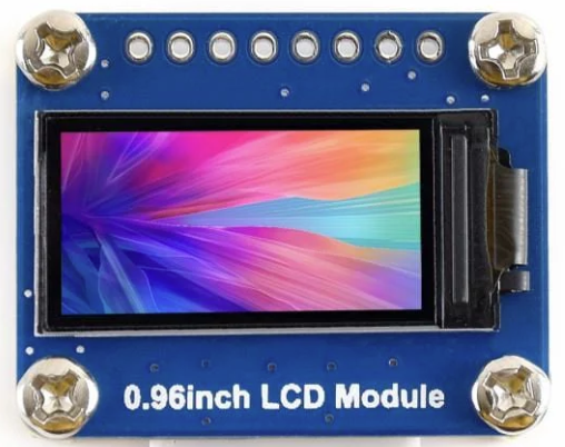
The 0.96" IPS LCD Display Module (160x80), manufactured by Waveshare (Part ID: WAV-15868), is a compact and versatile display designed for embedded systems. With its 0.96-inch diagonal screen, 160x80 pixel resolution, and IPS technology, this module delivers vibrant colors, wide viewing angles, and excellent clarity. It is ideal for applications requiring a small yet high-quality display, such as IoT devices, handheld instruments, and wearable electronics.
Explore Projects Built with 0.96" IPS LCD Display Module (160x80)


Explore Projects Built with 0.96" IPS LCD Display Module (160x80)
Common Applications
- IoT dashboards and status displays
- Wearable devices
- Portable measurement tools
- Compact user interfaces for embedded systems
- Educational and prototyping projects
Technical Specifications
Below are the key technical details of the 0.96" IPS LCD Display Module:
| Parameter | Specification |
|---|---|
| Manufacturer | Waveshare |
| Part ID | WAV-15868 |
| Display Type | IPS LCD |
| Screen Size | 0.96 inches |
| Resolution | 160x80 pixels |
| Interface | SPI |
| Operating Voltage | 3.3V / 5V |
| Operating Current | ~20mA (typical) |
| Viewing Angle | 160° (horizontal and vertical) |
| Backlight | LED |
| Dimensions | 27.5mm x 14.5mm x 2.4mm |
| Operating Temperature | -20°C to 70°C |
Pin Configuration
The module features a 7-pin interface for SPI communication. Below is the pinout description:
| Pin | Name | Description |
|---|---|---|
| 1 | GND | Ground connection |
| 2 | VCC | Power supply (3.3V or 5V) |
| 3 | SCL | Serial Clock Line (SPI clock input) |
| 4 | SDA | Serial Data Line (SPI data input) |
| 5 | RES | Reset pin (active low) |
| 6 | DC | Data/Command control pin |
| 7 | CS | Chip Select (active low) |
Usage Instructions
Connecting the Display to a Circuit
To use the 0.96" IPS LCD Display Module, connect it to a microcontroller (e.g., Arduino UNO) via the SPI interface. Below is a typical wiring guide for an Arduino UNO:
| Display Pin | Arduino Pin |
|---|---|
| GND | GND |
| VCC | 5V |
| SCL | D13 (SCK) |
| SDA | D11 (MOSI) |
| RES | D8 |
| DC | D9 |
| CS | D10 |
Important Considerations
- Voltage Compatibility: The module supports both 3.3V and 5V logic levels, making it compatible with most microcontrollers.
- SPI Speed: Ensure the SPI clock speed does not exceed the module's maximum supported frequency (typically 10 MHz).
- Reset Pin: Always initialize the display by toggling the RES pin during startup.
- Library Support: Use a compatible library (e.g., Adafruit GFX and ST7735 libraries) for easier integration.
Example Code for Arduino UNO
Below is an example Arduino sketch to initialize and display text on the module using the Adafruit GFX and ST7735 libraries:
#include <Adafruit_GFX.h>      // Core graphics library
#include <Adafruit_ST7735.h>   // Library for ST7735-based displays
#include <SPI.h>               // SPI library

// Define pin connections
#define TFT_CS   10  // Chip Select pin
#define TFT_RST  8   // Reset pin
#define TFT_DC   9   // Data/Command pin

// Initialize the display object
Adafruit_ST7735 tft = Adafruit_ST7735(TFT_CS, TFT_DC, TFT_RST);

void setup() {
  // Initialize serial communication for debugging
  Serial.begin(9600);
  Serial.println("Initializing display...");

  // Initialize the display
  tft.initR(INITR_MINI160x80);  // Use the correct initialization for 160x80
  tft.setRotation(1);          // Set display orientation (1 = landscape)

  // Clear the screen and set text properties
  tft.fillScreen(ST77XX_BLACK);  // Clear screen with black color
  tft.setTextColor(ST77XX_WHITE); // Set text color to white
  tft.setTextSize(1);            // Set text size (1 = smallest)

  // Display a message
  tft.setCursor(0, 0);           // Set cursor to top-left corner
  tft.println("Hello, World!");  // Print text to the display
}

void loop() {
  // Nothing to do here
}
Best Practices
- Use short and properly shielded wires for SPI connections to minimize noise.
- Avoid exposing the display to extreme temperatures or humidity.
- Handle the module carefully to prevent damage to the screen or pins.
Troubleshooting and FAQs
Common Issues and Solutions
Display Not Turning On
- Cause: Incorrect wiring or insufficient power supply.
- Solution: Double-check all connections and ensure the power supply provides adequate voltage and current.
No Output on the Screen
- Cause: Incorrect initialization or SPI communication failure.
- Solution: Verify the SPI connections and ensure the correct library and initialization code are used.
Flickering or Distorted Display
- Cause: Excessive SPI clock speed or noisy connections.
- Solution: Reduce the SPI clock speed and use shorter, shielded wires.
Partial or Incorrect Display
- Cause: Incorrect orientation or resolution settings.
- Solution: Ensure the correct initialization parameters (e.g.,
INITR_MINI160x80) are used.
FAQs
Q: Can this display be used with 3.3V microcontrollers like ESP32?
A: Yes, the module supports both 3.3V and 5V logic levels, making it compatible with 3.3V microcontrollers.
Q: Is the backlight brightness adjustable?
A: The backlight is not directly adjustable, but you can control its brightness by adding a PWM circuit to the VCC line.
Q: What is the maximum SPI clock speed supported?
A: The module typically supports SPI clock speeds up to 10 MHz. Check the datasheet for exact details.
Q: Can I display images on this module?
A: Yes, you can display images by converting them to a compatible format (e.g., BMP) and using the appropriate library functions.
Q: Does the module come with a protective screen cover?
A: Some versions may include a protective film. Check with the supplier for details.