How to Use motor: Examples, Pinouts, and Specs
Introduction
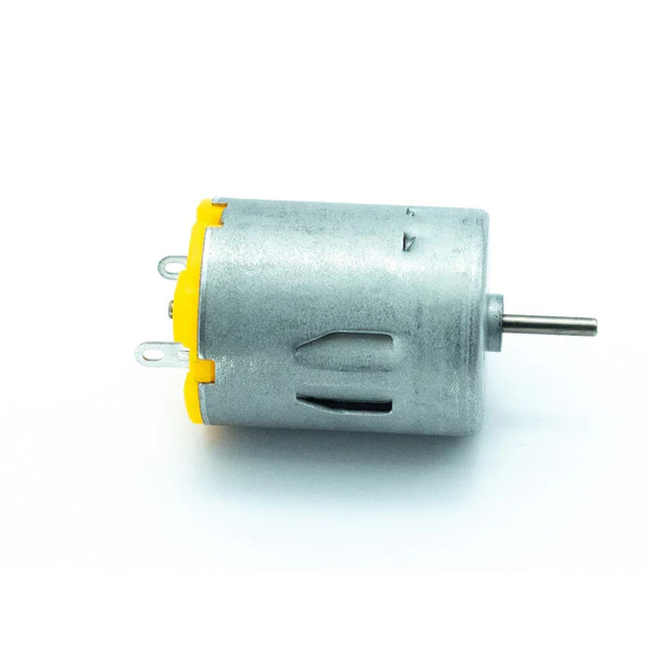
The ZA QWE motor is an electromechanical device designed to convert electrical energy into mechanical energy, specifically rotational motion. This motor is suitable for a wide range of applications, including robotics, automation systems, hobby projects, and educational purposes.
Explore Projects Built with motor

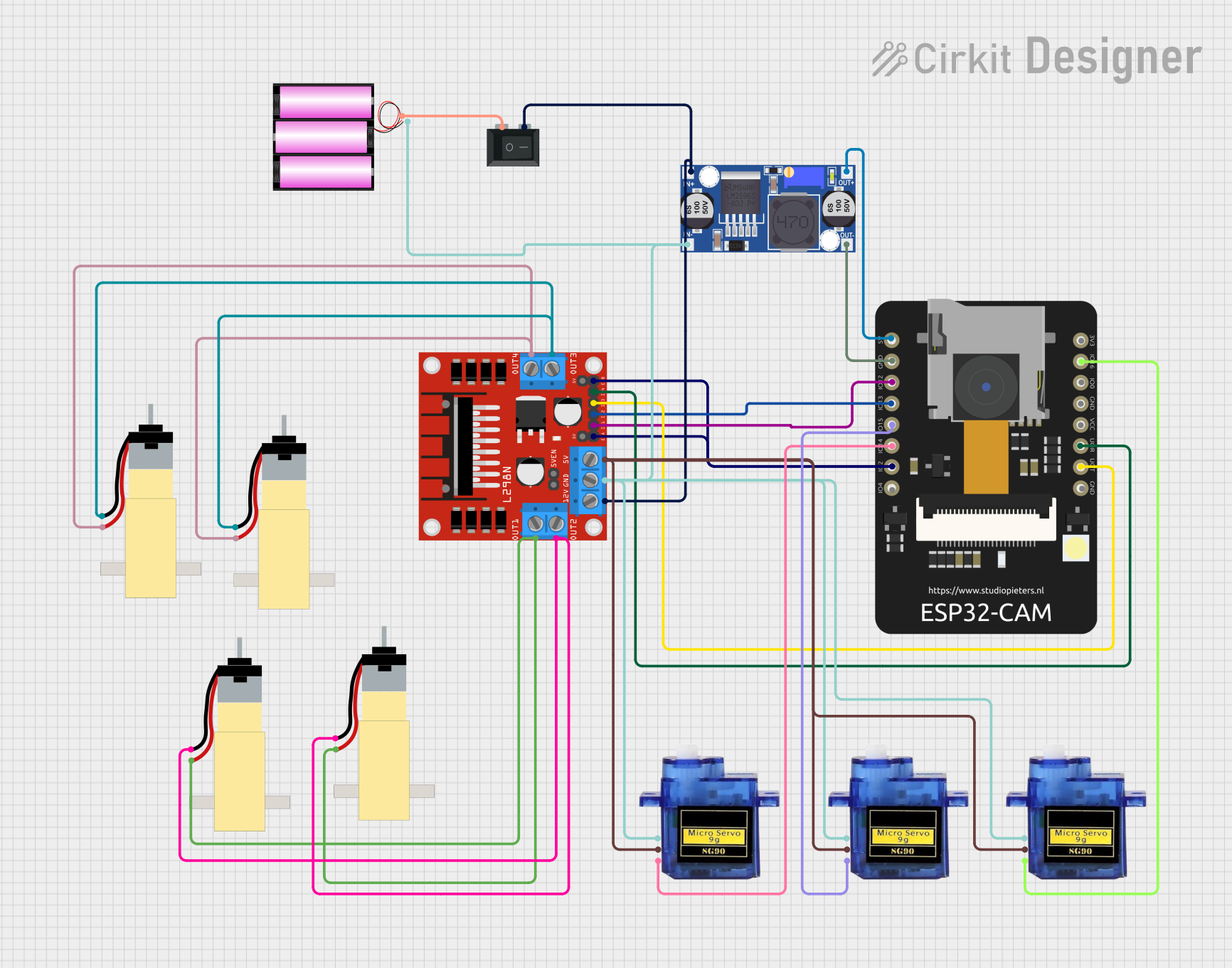
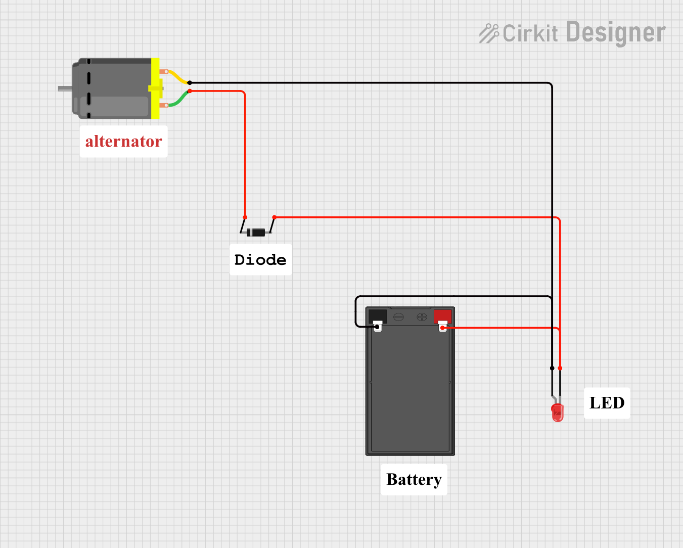
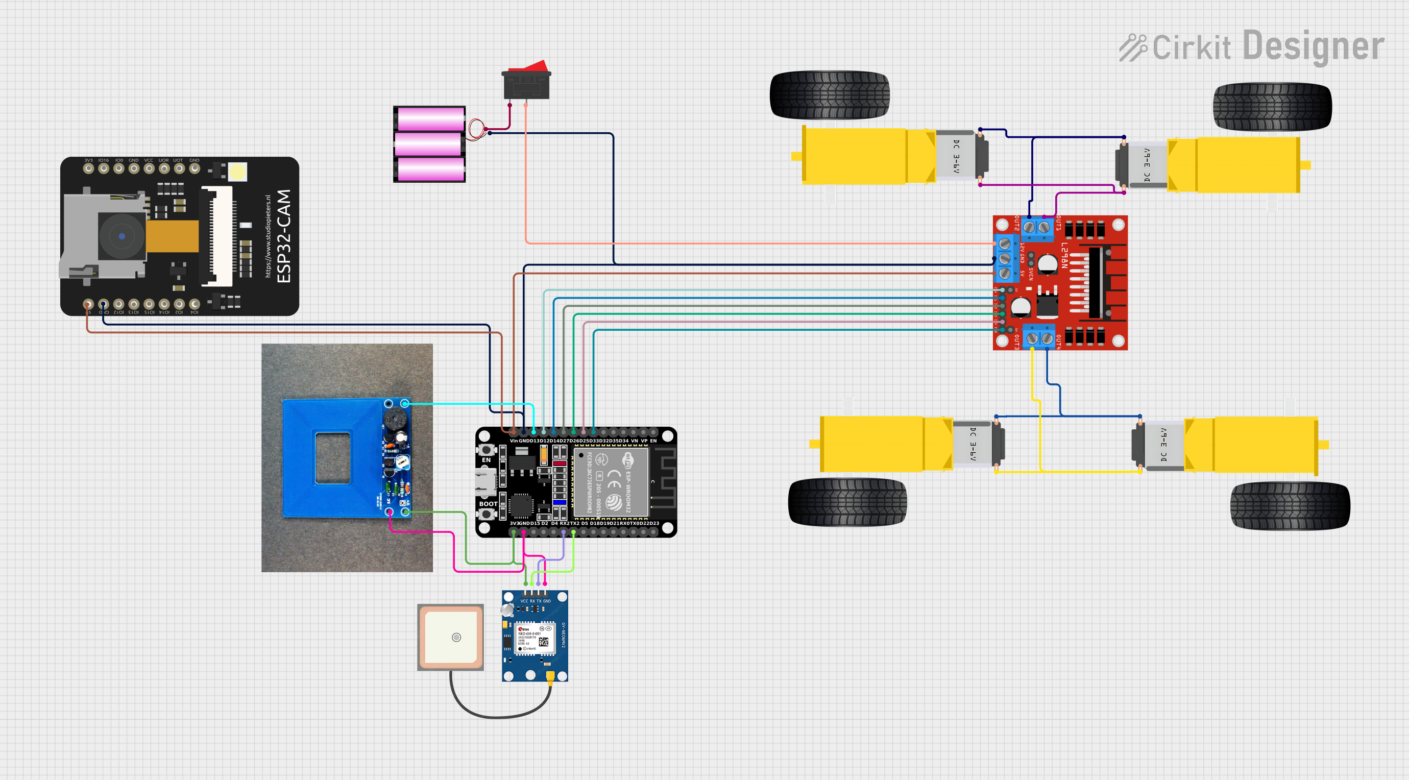
Explore Projects Built with motor
Common Applications and Use Cases
- Robotics: Actuating wheels, joints, and manipulators.
- Automation: Conveyor belts, lifting mechanisms, and process control.
- Hobby Projects: DIY vehicles, model airplanes, and boats.
- Education: Learning about electromechanical systems and motor control.
Technical Specifications
Key Technical Details
- Voltage Range: 3.0V to 12.0V
- Nominal Voltage: 6.0V
- Current (No Load): 100mA
- Current (Max Load): 1.2A
- Speed (No Load): 15000 RPM
- Torque (Max): 20 g·cm
- Power Ratings: 1.2W (at nominal voltage)
Pin Configuration and Descriptions
| Pin Number | Description | Notes |
|---|---|---|
| 1 | Motor Terminal (+) | Connect to positive power supply |
| 2 | Motor Terminal (−) | Connect to ground |
Usage Instructions
How to Use the Component in a Circuit
- Power Supply: Ensure that the power supply matches the motor's voltage requirements. Overvoltage can damage the motor, while undervoltage may result in insufficient performance.
- Motor Driver: Use a motor driver or an H-bridge circuit to control the motor's direction and speed. Direct connection to a microcontroller's GPIO pin is not recommended due to current limitations.
- PWM Control: For speed control, use Pulse Width Modulation (PWM) through a motor driver. This allows for precise speed adjustments without sacrificing torque.
- Mounting: Secure the motor firmly to prevent vibrations and ensure the shaft is aligned with the load to avoid undue stress.
Important Considerations and Best Practices
- Current Draw: Monitor the current draw to prevent overheating. If the motor stalls, the current can spike and cause damage.
- Heat Dissipation: Ensure adequate ventilation around the motor to dissipate heat during operation.
- Electrical Noise: Motors can generate electrical noise; use capacitors across the terminals to minimize interference with other electronics.
Troubleshooting and FAQs
Common Issues Users Might Face
- Motor Does Not Start: Check power supply and connections. Ensure the motor driver is functioning correctly.
- Motor Overheats: Reduce load or duty cycle. Check for mechanical obstructions.
- Insufficient Torque: Verify that the motor is operating within its specified voltage and current range.
Solutions and Tips for Troubleshooting
- Intermittent Operation: Inspect wiring for loose connections and ensure terminals are not shorting.
- Noise Reduction: Add a snubber circuit or flyback diode to mitigate voltage spikes caused by inductive loads.
FAQs
Q: Can I reverse the motor's direction? A: Yes, by reversing the polarity of the voltage applied to the motor terminals or using an H-bridge circuit.
Q: What is the lifespan of the motor? A: The lifespan depends on the operating conditions, such as load, voltage, and duty cycle. Proper usage within specified limits will ensure a longer lifespan.
Example Code for Arduino UNO
// Example code to control ZA QWE Motor with Arduino UNO and a simple H-bridge

#include <Arduino.h>

const int motorPin1 = 3; // H-bridge leg 1 (pin 2, 1A)
const int motorPin2 = 4; // H-bridge leg 2 (pin 7, 2A)
const int enablePin = 9; // H-bridge enable pin

void setup() {
  pinMode(motorPin1, OUTPUT);
  pinMode(motorPin2, OUTPUT);
  pinMode(enablePin, OUTPUT);
}

void loop() {
  // Rotate motor clockwise
  digitalWrite(motorPin1, HIGH);
  digitalWrite(motorPin2, LOW);
  analogWrite(enablePin, 128); // Set speed (0-255)
  delay(1000);

  // Stop motor
  digitalWrite(enablePin, LOW);
  delay(1000);

  // Rotate motor counterclockwise
  digitalWrite(motorPin1, LOW);
  digitalWrite(motorPin2, HIGH);
  analogWrite(enablePin, 128); // Set speed (0-255)
  delay(1000);

  // Stop motor
  digitalWrite(enablePin, LOW);
  delay(1000);
}
Note: The above code assumes the use of a standard H-bridge circuit for motor control. Adjust the pin numbers and PWM values as needed for your specific setup. Always ensure that the motor control circuitry can handle the current requirements of the motor.