How to Use Ground Rod: Examples, Pinouts, and Specs

Introduction
A ground rod is a conductive rod, typically made of copper or galvanized steel, that is driven into the ground to provide a low-resistance path for electrical currents. It plays a critical role in grounding electrical systems, ensuring safety by directing fault currents or stray electrical charges safely into the earth. Ground rods are essential components in electrical installations, protecting both equipment and individuals from electrical hazards.
Explore Projects Built with Ground Rod

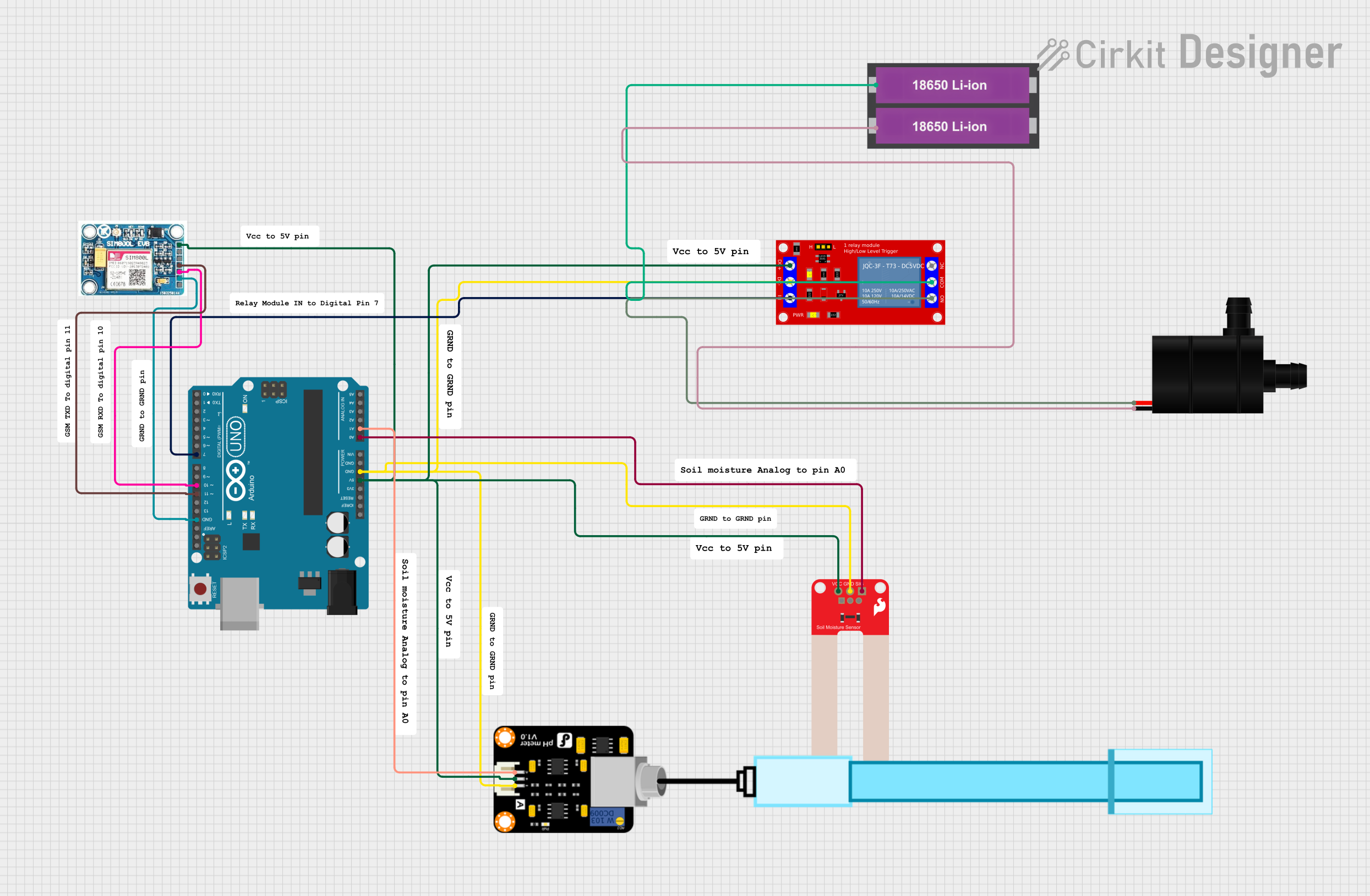
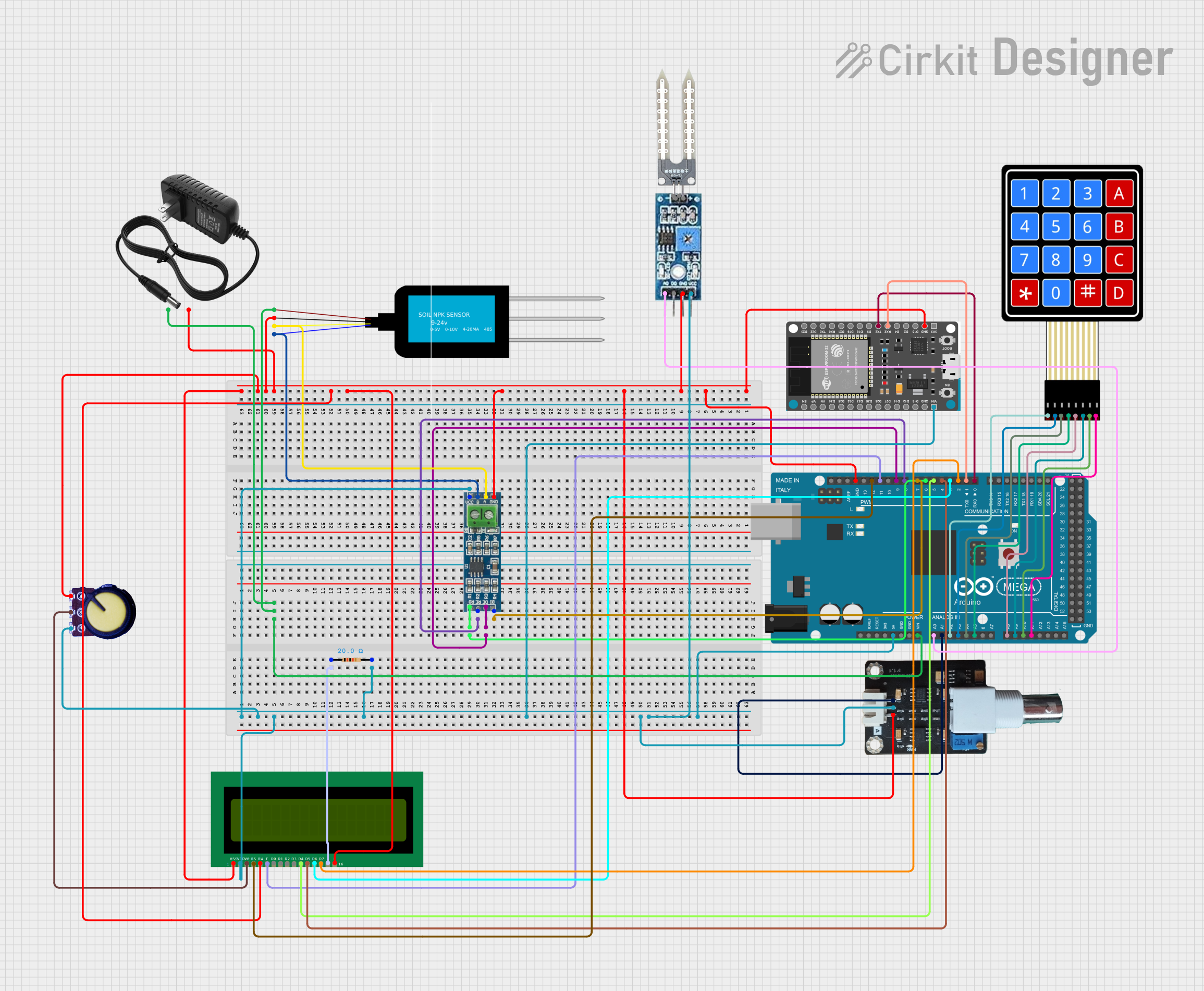
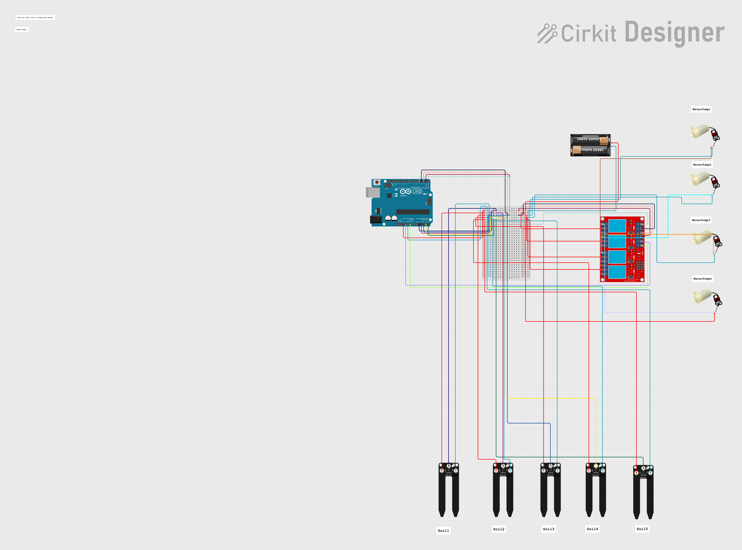
Explore Projects Built with Ground Rod
Common Applications and Use Cases
- Grounding residential and commercial electrical systems.
- Lightning protection systems.
- Grounding for telecommunications and data centers.
- Electrical safety in industrial equipment and machinery.
- Grounding renewable energy systems, such as solar panels and wind turbines.
Technical Specifications
Key Technical Details
| Parameter | Specification |
|---|---|
| Material | Copper or galvanized steel |
| Length | Typically 4 to 10 feet (1.2 to 3 meters) |
| Diameter | Commonly 5/8 inch (16 mm) or 3/4 inch (19 mm) |
| Resistance Requirement | Less than 25 ohms (as per NEC standards) |
| Coating (if applicable) | Copper-clad or hot-dip galvanized |
| Installation Depth | Fully buried, with the top flush or below ground level |
Pin Configuration and Descriptions
Ground rods do not have pins like electronic components, but they feature connection points for grounding conductors. Below is a description of the connection interface:
| Connection Point | Description |
|---|---|
| Ground Clamp | Secures the grounding conductor to the rod. |
| Grounding Conductor | Wire that connects the rod to the electrical system. |
Usage Instructions
How to Use the Ground Rod in a Circuit
- Select the Appropriate Ground Rod: Choose a rod that meets local electrical codes and standards (e.g., NEC in the U.S.).
- Prepare the Installation Site: Identify a location with good soil conductivity, away from obstructions like rocks or building foundations.
- Drive the Rod into the Ground: Use a hammer, sledgehammer, or specialized ground rod driver to drive the rod vertically into the soil. Ensure the rod is fully buried, with the top flush or slightly below ground level.
- Connect the Grounding Conductor:
- Use a ground clamp to securely attach the grounding conductor to the rod.
- Ensure the connection is tight and corrosion-resistant.
- Test the Grounding System: Measure the resistance of the grounding system using an earth resistance tester. The resistance should typically be less than 25 ohms.
Important Considerations and Best Practices
- Soil Conductivity: Moist, loamy soil provides better conductivity than dry, sandy, or rocky soil. If the soil is poor, consider using multiple ground rods connected in parallel.
- Corrosion Resistance: Use copper-clad or galvanized rods to prevent corrosion over time.
- Safety: Always turn off the power supply before working on the grounding system.
- Compliance: Follow local electrical codes and standards for grounding installations.
Example: Connecting a Ground Rod to an Arduino UNO
While ground rods are not directly connected to Arduino boards, they can be used to ground the power supply or shield sensitive circuits. Below is an example of grounding a power supply for an Arduino project:
// Example: Arduino project with grounded power supply
// Ensure the power supply's ground is connected to the ground rod
// to minimize electrical noise and improve safety.

void setup() {
  // Initialize serial communication for debugging
  Serial.begin(9600);

  // Example: Reading a sensor value
  pinMode(A0, INPUT); // Set analog pin A0 as input
}

void loop() {
  int sensorValue = analogRead(A0); // Read sensor value
  Serial.println(sensorValue); // Print the value to the serial monitor

  delay(1000); // Wait for 1 second
}

// Note: Ensure the power supply's ground is securely connected to the
// ground rod using a grounding conductor and clamp. This reduces noise
// and ensures proper grounding for the entire system.
Troubleshooting and FAQs
Common Issues Users Might Face
High Ground Resistance:
- Cause: Poor soil conductivity or insufficient rod depth.
- Solution: Drive the rod deeper or install additional rods in parallel.
Corrosion of the Ground Rod:
- Cause: Exposure to corrosive soil or improper material selection.
- Solution: Use copper-clad or galvanized rods and inspect periodically.
Loose Grounding Connections:
- Cause: Improperly secured ground clamp or conductor.
- Solution: Tighten the clamp and ensure a secure, corrosion-resistant connection.
Electrical Noise in the System:
- Cause: Inadequate grounding or interference from nearby equipment.
- Solution: Verify the grounding system and ensure proper shielding of sensitive circuits.
FAQs
Q1: Can I use a shorter ground rod?
A1: Shorter rods may not meet resistance requirements. Always follow local codes, which typically require rods to be at least 8 feet long.
Q2: How do I test the ground rod's effectiveness?
A2: Use an earth resistance tester to measure the resistance. The value should be less than 25 ohms for most applications.
Q3: Can I install the ground rod horizontally?
A3: Vertical installation is preferred for better conductivity. Horizontal installation is only used in specific cases where vertical placement is not feasible.
Q4: Do I need multiple ground rods?
A4: If the resistance of a single rod is too high, additional rods can be installed in parallel to reduce the overall resistance.
By following this documentation, users can ensure safe and effective installation and use of ground rods in their electrical systems.