Cirkit Designer Logo
Cirkit Designer
Your all-in-one circuit design IDE
Home / 
Component Documentation

How to Use 2 pin header: Examples, Pinouts, and Specs
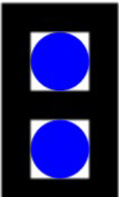

Image of 2 pin header
Cirkit Designer LogoDesign with 2 pin header in Cirkit Designer

Introduction

A 2 pin header is a type of electrical connector consisting of two metal pins that can be used to connect wires or other components in a circuit. It is commonly used for making connections to printed circuit boards (PCBs) and allows for easy disconnection and reconnection. These headers are widely used in electronics for prototyping, modular designs, and interfacing with external devices.

Explore Projects Built with 2 pin header

Use Cirkit Designer to design, explore, and prototype these projects online. Some projects support real-time simulation. Click "Open Project" to start designing instantly!
5-Pin Connector Synchronization Circuit
Image of UMB_Cable: A project utilizing 2 pin header in a practical application
This circuit consists of four 5-pin connectors, where two of the connectors are fully interconnected pin-to-pin. The purpose of this setup could be to create a parallel connection between the two 5-pin connectors, possibly for signal distribution or redundancy.
Cirkit Designer LogoOpen Project in Cirkit Designer
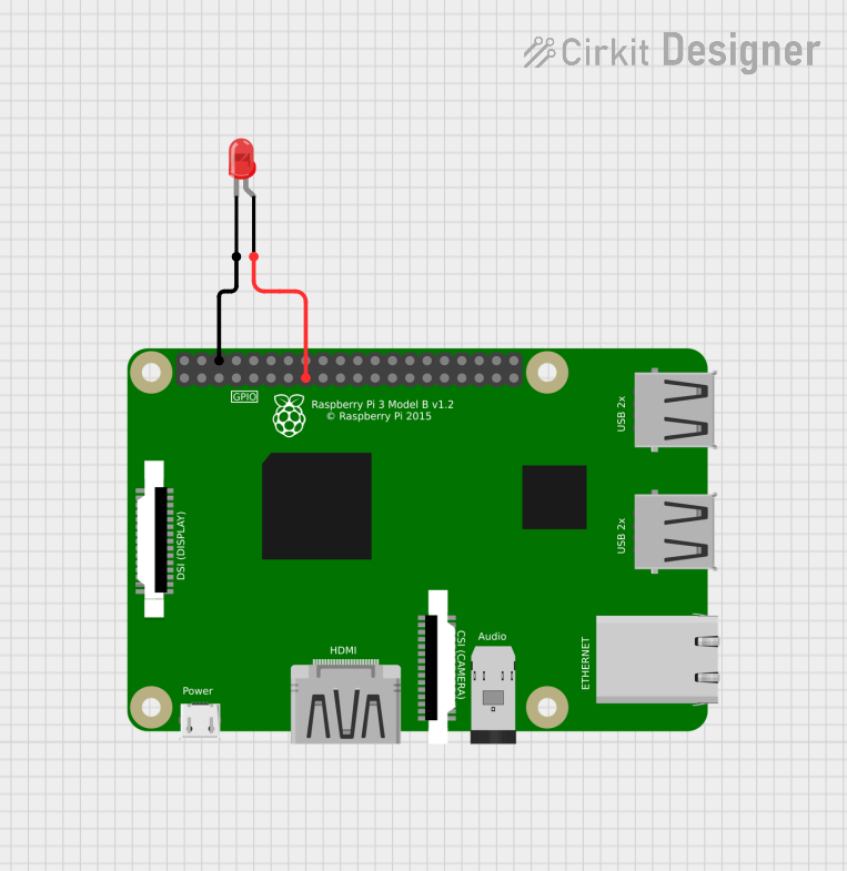
Raspberry Pi-Controlled Red LED Indicator
Image of ras1: A project utilizing 2 pin header in a practical application
This circuit consists of a Raspberry Pi 3B microcontroller connected to a two-pin red LED. The GPIO22 pin of the Raspberry Pi is connected to the anode of the LED, and one of the Raspberry Pi's GND pins is connected to the cathode of the LED. This setup allows the Raspberry Pi to control the LED, turning it on and off by toggling the GPIO22 pin.
Cirkit Designer LogoOpen Project in Cirkit Designer
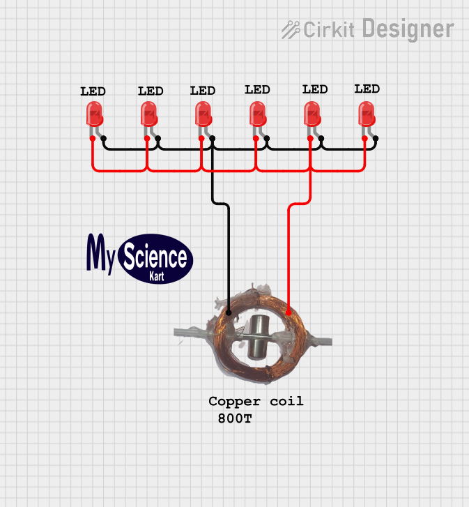
LED Array with Inductive Power Transfer
Image of Wind Mill: A project utilizing 2 pin header in a practical application
The circuit consists of multiple red two-pin LEDs connected in parallel, with all cathodes tied together and all anodes tied together. A copper coil is also connected in parallel with the LEDs. There is no control circuitry or power regulation components indicated, and no embedded code provided, suggesting this is a simple illumination circuit possibly intended for inductive power transfer given the presence of the copper coil.
Cirkit Designer LogoOpen Project in Cirkit Designer
Dual 5V Power Supply Distribution Circuit with Toggle Switch Control
Image of rfdriver: A project utilizing 2 pin header in a practical application
This circuit consists of two 5V 5A power supplies connected to an AC wall plug point, providing DC output through a 12-way connector. The ground connections from both power supplies are interconnected and also connected to the ground pins of two toggle switches. The DC outputs from the power supplies are separately connected to different pins on the 12-way connector, with each power supply output being switchable via one of the toggle switches.
Cirkit Designer LogoOpen Project in Cirkit Designer

Explore Projects Built with 2 pin header

Use Cirkit Designer to design, explore, and prototype these projects online. Some projects support real-time simulation. Click "Open Project" to start designing instantly!
Image of UMB_Cable: A project utilizing 2 pin header in a practical application
5-Pin Connector Synchronization Circuit
This circuit consists of four 5-pin connectors, where two of the connectors are fully interconnected pin-to-pin. The purpose of this setup could be to create a parallel connection between the two 5-pin connectors, possibly for signal distribution or redundancy.
Cirkit Designer LogoOpen Project in Cirkit Designer
Image of ras1: A project utilizing 2 pin header in a practical application
Raspberry Pi-Controlled Red LED Indicator
This circuit consists of a Raspberry Pi 3B microcontroller connected to a two-pin red LED. The GPIO22 pin of the Raspberry Pi is connected to the anode of the LED, and one of the Raspberry Pi's GND pins is connected to the cathode of the LED. This setup allows the Raspberry Pi to control the LED, turning it on and off by toggling the GPIO22 pin.
Cirkit Designer LogoOpen Project in Cirkit Designer
Image of Wind Mill: A project utilizing 2 pin header in a practical application
LED Array with Inductive Power Transfer
The circuit consists of multiple red two-pin LEDs connected in parallel, with all cathodes tied together and all anodes tied together. A copper coil is also connected in parallel with the LEDs. There is no control circuitry or power regulation components indicated, and no embedded code provided, suggesting this is a simple illumination circuit possibly intended for inductive power transfer given the presence of the copper coil.
Cirkit Designer LogoOpen Project in Cirkit Designer
Image of rfdriver: A project utilizing 2 pin header in a practical application
Dual 5V Power Supply Distribution Circuit with Toggle Switch Control
This circuit consists of two 5V 5A power supplies connected to an AC wall plug point, providing DC output through a 12-way connector. The ground connections from both power supplies are interconnected and also connected to the ground pins of two toggle switches. The DC outputs from the power supplies are separately connected to different pins on the 12-way connector, with each power supply output being switchable via one of the toggle switches.
Cirkit Designer LogoOpen Project in Cirkit Designer

Common Applications and Use Cases

  • Connecting power supply lines to PCBs
  • Interfacing sensors or modules with microcontrollers
  • Creating modular connections in prototyping
  • Debugging and testing circuits
  • Extending or bridging connections in electronic systems

Technical Specifications

Key Technical Details

  • Number of Pins: 2
  • Pin Spacing (Pitch): Typically 2.54 mm (0.1 inch)
  • Current Rating: Up to 3A (varies by manufacturer)
  • Voltage Rating: Up to 250V (varies by manufacturer)
  • Material:
    • Pins: Tin-plated or gold-plated brass
    • Housing: Plastic (commonly nylon or PBT)
  • Operating Temperature: -40°C to 105°C (typical)

Pin Configuration and Descriptions

Pin Number Description
1 First connection terminal
2 Second connection terminal

Usage Instructions

How to Use the Component in a Circuit

  1. Soldering to a PCB:
    • Align the 2 pin header with the holes on the PCB.
    • Solder each pin securely to the PCB pads, ensuring no solder bridges form.
  2. Connecting Wires:
    • Use female connectors or jumper wires to connect to the pins.
    • Ensure a snug fit to maintain a reliable electrical connection.
  3. Interfacing with Microcontrollers:
    • Use the 2 pin header to connect external modules or sensors to microcontroller boards like Arduino.
    • Ensure proper polarity when connecting power or signal lines.

Important Considerations and Best Practices

  • Pin Alignment: Ensure the pins are straight and properly aligned before soldering.
  • Current and Voltage Ratings: Do not exceed the specified ratings to avoid overheating or damage.
  • Secure Connections: Use locking connectors or heat-shrink tubing for added stability in high-vibration environments.
  • Avoid Short Circuits: Ensure no conductive materials bridge the two pins.

Example: Connecting a 2 Pin Header to an Arduino UNO

Below is an example of using a 2 pin header to connect an LED to an Arduino UNO:

// Example: Blinking an LED connected via a 2 pin header to Arduino UNO
// Connect the positive leg of the LED to pin 13 on the Arduino
// Connect the negative leg of the LED to GND via a 2 pin header

void setup() {
  pinMode(13, OUTPUT); // Set pin 13 as an output
}

void loop() {
  digitalWrite(13, HIGH); // Turn the LED on
  delay(1000);            // Wait for 1 second
  digitalWrite(13, LOW);  // Turn the LED off
  delay(1000);            // Wait for 1 second
}

Troubleshooting and FAQs

Common Issues Users Might Face

  1. Loose Connections:

    • Problem: The wires or connectors are not making proper contact with the pins.
    • Solution: Ensure the connectors are securely attached and check for bent pins.
  2. Overheating:

    • Problem: The header gets hot during operation.
    • Solution: Verify that the current and voltage ratings are not being exceeded.
  3. Soldering Problems:

    • Problem: Poor solder joints or solder bridges between pins.
    • Solution: Re-solder the connections, ensuring clean and precise soldering.
  4. Polarity Issues:

    • Problem: Incorrect connection of power or signal lines.
    • Solution: Double-check the wiring and ensure proper polarity.

FAQs

  • Q: Can I use a 2 pin header for high-frequency signals?
    A: Yes, but ensure the header and PCB layout are designed to minimize signal loss or interference.

  • Q: Are 2 pin headers reusable?
    A: Yes, they can be reused if removed carefully without damaging the pins or PCB.

  • Q: What tools are needed to work with 2 pin headers?
    A: Common tools include a soldering iron, solder, wire cutters, and jumper wires or female connectors.

  • Q: Can I use a 2 pin header for power connections?
    A: Yes, as long as the current and voltage ratings are not exceeded.