How to Use Adafruit MAX9814 Electret Microphone Amplifier: Examples, Pinouts, and Specs
Introduction
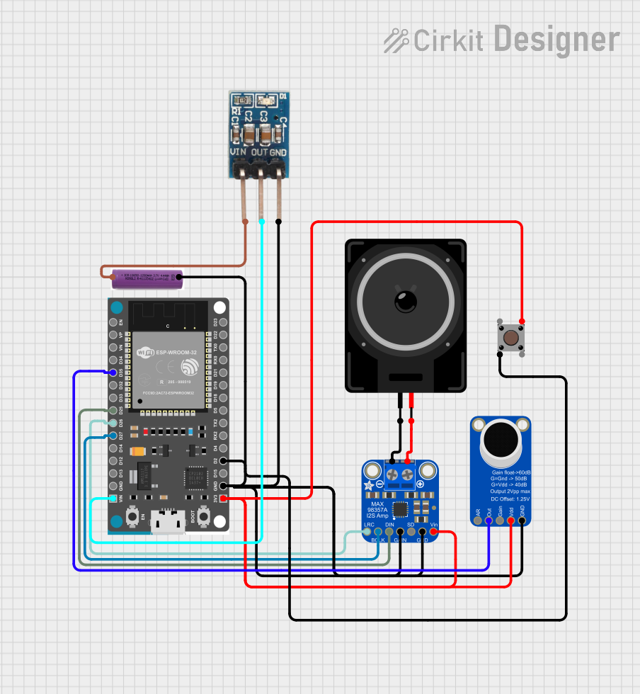
The Adafruit MAX9814 Electret Microphone Amplifier is a specialized audio amplification module tailored for use with electret condenser microphones. It simplifies the process of integrating an audio input into various electronic projects, including voice recognition systems, audio recording setups, and interactive installations. The module's automatic gain control (AGC) ensures consistent audio levels, making it ideal for applications where ambient noise levels vary significantly.
Explore Projects Built with Adafruit MAX9814 Electret Microphone Amplifier
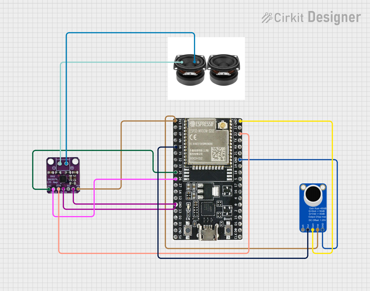
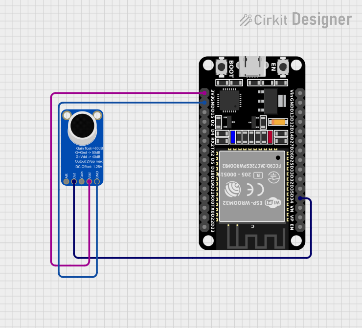
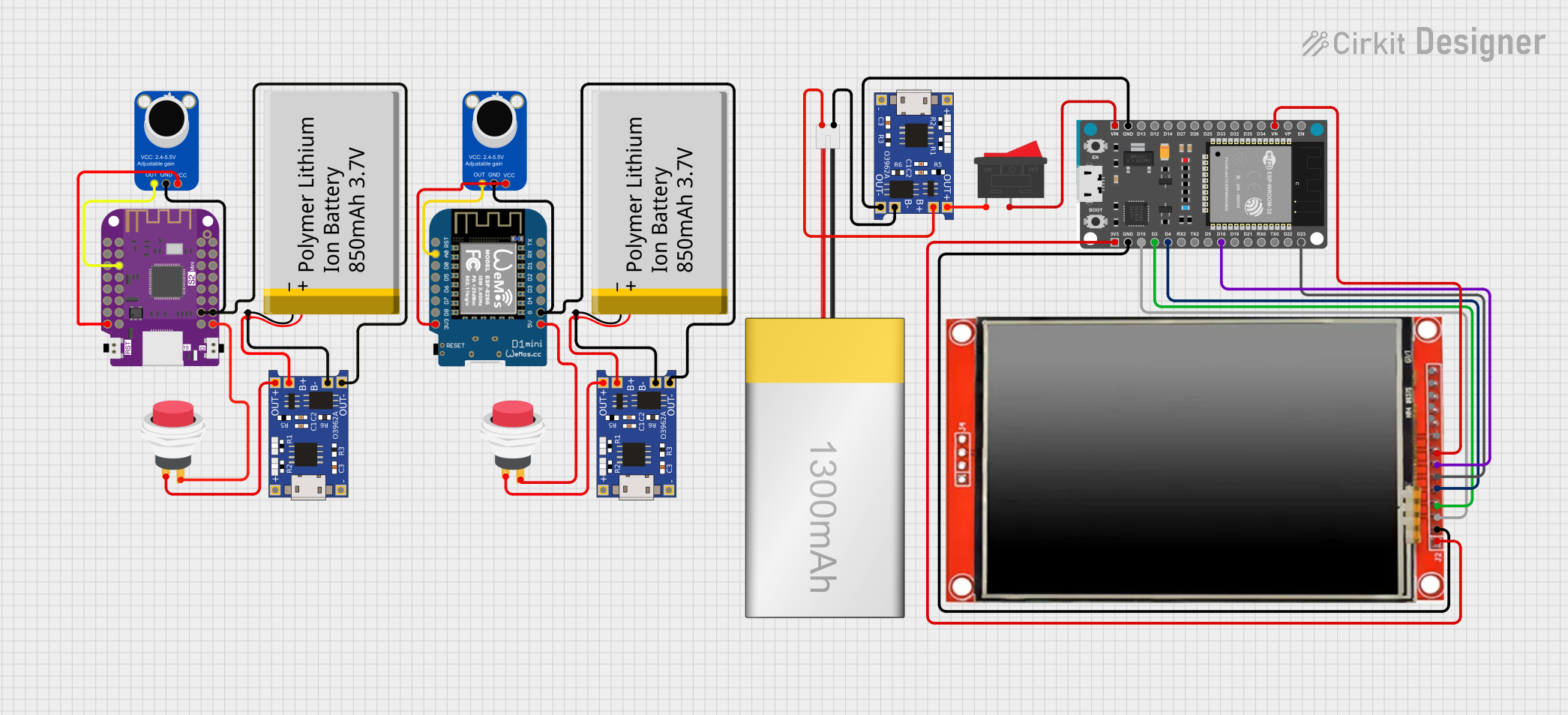
Explore Projects Built with Adafruit MAX9814 Electret Microphone Amplifier
Common Applications and Use Cases
- Voice-activated systems
- Audio recording devices
- Sound level detection
- Interactive art installations
- Noise level monitoring
Technical Specifications
Key Technical Details
- Supply Voltage: 2.7V-5.5V
- Current Consumption: 3mA
- Gain Settings: 40dB, 50dB, 60dB (selectable)
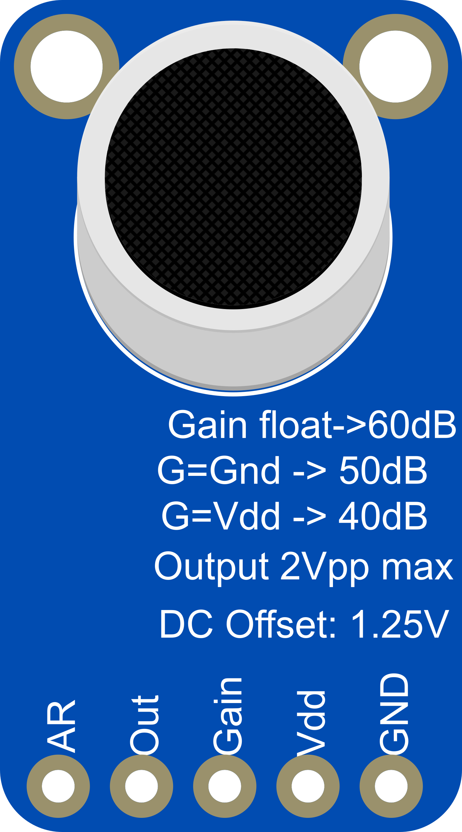
- Output: 2Vpp on 1.25V bias
- Frequency Response: 20Hz - 20kHz
- AGC Compression Ratio: 1:3
Pin Configuration and Descriptions
| Pin Number | Name | Description |
|---|---|---|
| 1 | VDD | Power supply (2.7V-5.5V) |
| 2 | GND | Ground connection |
| 3 | OUT | Audio output signal |
| 4 | GAIN | Gain selection pin |
| 5 | AR | Attack/Release control |
Usage Instructions
How to Use the Component in a Circuit
- Power Supply: Connect the VDD pin to a 2.7V-5.5V power source and the GND pin to the ground.
- Microphone Connection: Attach an electret microphone to the input terminals of the MAX9814 module.
- Gain Setting: Select the desired gain (40dB, 50dB, or 60dB) by connecting the GAIN pin to VDD, GND, or leaving it unconnected (floating), respectively.
- Audio Output: Connect the OUT pin to the audio input of your recording or processing device.
- Attack/Release Control: Optionally, connect a capacitor to the AR pin to adjust the AGC attack and release times.
Important Considerations and Best Practices
- Ensure that the power supply voltage does not exceed the maximum rating of 5.5V.
- Use a decoupling capacitor close to the VDD pin to filter out power supply noise.
- Keep audio signal paths as short as possible to minimize interference.
- If using with a microcontroller like an Arduino, ensure that the audio signal is properly conditioned for analog-to-digital conversion.
Example Connection with Arduino UNO
// Example code for interfacing the Adafruit MAX9814 with an Arduino UNO

const int audioInputPin = A0; // Connect the OUT pin of MAX9814 to A0 on Arduino

void setup() {
  Serial.begin(9600);
}

void loop() {
  int audioLevel = analogRead(audioInputPin); // Read the audio level from the microphone
  Serial.println(audioLevel); // Output the audio level to the Serial Monitor
  delay(10); // Short delay for stability
}
Troubleshooting and FAQs
Common Issues
- Low Audio Output: Check the gain setting and ensure the microphone is functioning correctly.
- Distorted Audio: Ensure the power supply is stable and within the specified voltage range.
- No Audio Signal: Verify all connections, including the microphone and audio output wiring.
Solutions and Tips for Troubleshooting
- Use shielded cables for audio connections to reduce noise pickup.
- If experiencing erratic behavior, add a 0.1uF capacitor between VDD and GND.
- For AGC issues, adjust the capacitor value at the AR pin to fine-tune the response.
FAQs
Q: Can I disable the AGC feature? A: The AGC is built into the MAX9814 and cannot be disabled. However, you can influence its behavior with the AR pin.
Q: What should I do if the audio signal is too weak or too strong? A: Adjust the gain setting by changing the connection on the GAIN pin.
Q: Is this module compatible with digital microcontrollers like the Raspberry Pi? A: Yes, but you may need an analog-to-digital converter (ADC) to process the audio signal.
Q: Can I use this amplifier with a dynamic microphone? A: The MAX9814 is designed for electret microphones, which include a built-in preamp. A dynamic microphone may require a different preamplifier.
Remember, this documentation is a starting point. Always consult the MAX9814 datasheet for comprehensive details and contact the manufacturer or community forums for additional support.