How to Use SERVO: Examples, Pinouts, and Specs
Introduction
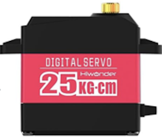
A servo is a rotary actuator that allows for precise control of angular position, velocity, and acceleration. It consists of a motor coupled to a sensor for position feedback, along with a control circuit. Servos are widely used in robotics, automation, and remote-controlled systems for tasks requiring accurate and repeatable movement. Their ability to hold a position and respond to control signals makes them ideal for applications such as robotic arms, camera gimbals, and model vehicles.
Explore Projects Built with SERVO

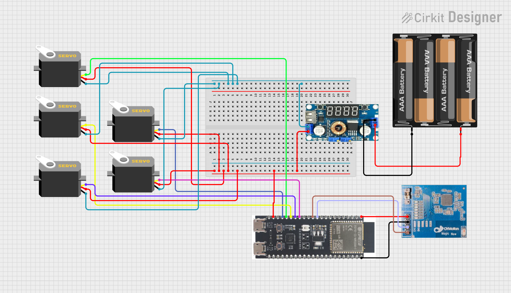

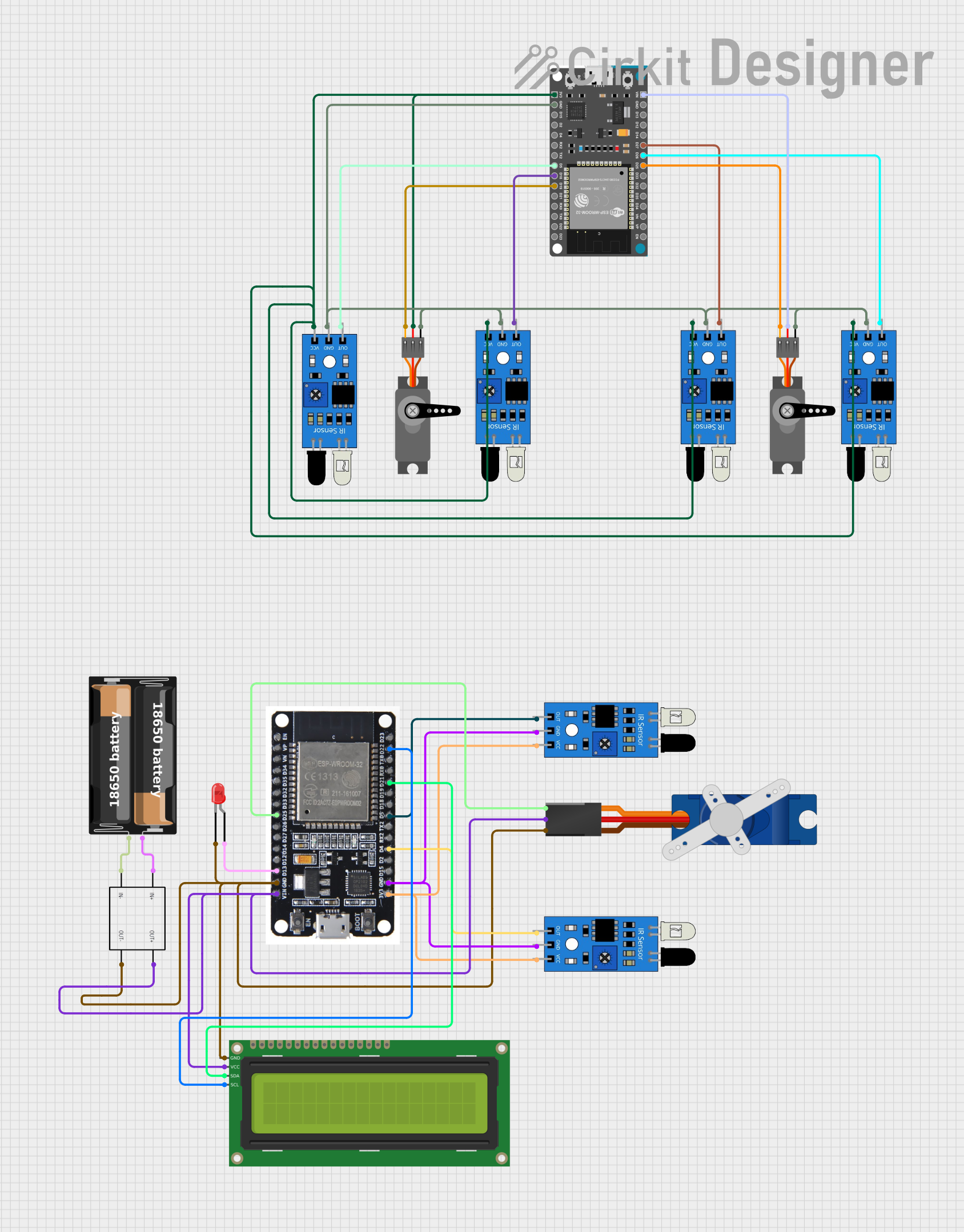
Explore Projects Built with SERVO
Technical Specifications
Below are the general technical specifications for a standard hobby servo. Note that specifications may vary depending on the specific model and manufacturer.
General Specifications
- Operating Voltage: 4.8V to 6.0V (typical)
- Current Draw (Idle): ~10 mA
- Current Draw (Operating): 100-500 mA (depending on load)
- Torque: 1.5 kg-cm to 20 kg-cm (varies by model)
- Rotation Range: 0° to 180° (standard), 360° for continuous rotation servos
- Signal Type: Pulse Width Modulation (PWM)
- Control Signal Pulse Width: 1 ms (0°), 1.5 ms (90°), 2 ms (180°)
- Response Time: ~0.1-0.2 seconds per 60° (varies by model)
Pin Configuration
The servo typically has three wires for connection. The pinout is as follows:
| Pin | Wire Color | Description |
|---|---|---|
| 1 | Brown/Black | Ground (GND) |
| 2 | Red | Power Supply (VCC) |
| 3 | Orange/White | Signal (PWM control input) |
Usage Instructions
How to Use a Servo in a Circuit
- Power the Servo: Connect the red wire to a 5V or 6V power source, and the black/brown wire to ground.
- Control Signal: Connect the orange/white wire to a PWM-capable pin on your microcontroller (e.g., Arduino).
- PWM Signal: Send a PWM signal to the servo to control its position. The pulse width determines the angle:
- 1 ms pulse: 0° position
- 1.5 ms pulse: 90° position (center)
- 2 ms pulse: 180° position
Important Considerations
- Power Supply: Ensure the power supply can handle the servo's current draw, especially under load.
- Signal Voltage: Verify that the control signal voltage matches the servo's requirements (typically 3.3V or 5V).
- Avoid Overloading: Do not exceed the servo's torque rating to prevent damage.
- Continuous Rotation Servos: For these, the PWM signal controls speed and direction rather than position.
Example: Controlling a Servo with Arduino UNO
Below is an example of how to control a standard servo using an Arduino UNO:
#include <Servo.h> // Include the Servo library

Servo myServo; // Create a Servo object

void setup() {
  myServo.attach(9); // Attach the servo to pin 9
}

void loop() {
  myServo.write(0); // Move servo to 0 degrees
  delay(1000);      // Wait for 1 second

  myServo.write(90); // Move servo to 90 degrees
  delay(1000);       // Wait for 1 second

  myServo.write(180); // Move servo to 180 degrees
  delay(1000);        // Wait for 1 second
}
Best Practices
- Use a separate power supply for the servo if it draws significant current.
- Avoid sending rapid, large position changes to prevent mechanical stress.
- Calibrate the servo if necessary to ensure accurate positioning.
Troubleshooting and FAQs
Common Issues and Solutions
Servo Not Moving
- Cause: No PWM signal or incorrect wiring.
- Solution: Verify the signal connection and ensure the PWM pin is configured correctly.
Servo Jitters or Vibrates
- Cause: Electrical noise or insufficient power supply.
- Solution: Use a capacitor across the power lines to filter noise and ensure the power supply can handle the current draw.
Servo Overheating
- Cause: Overloading or continuous operation at high torque.
- Solution: Reduce the load or allow the servo to rest periodically.
Servo Moves Erratically
- Cause: Incorrect PWM signal or interference.
- Solution: Check the PWM signal timing and ensure proper grounding.
FAQs
Q: Can I connect multiple servos to a single microcontroller?
- A: Yes, but ensure the microcontroller has enough PWM pins and the power supply can handle the combined current draw.
Q: What is the difference between a standard and a continuous rotation servo?
- A: A standard servo controls position within a range (e.g., 0° to 180°), while a continuous rotation servo controls speed and direction.
Q: Can I power a servo directly from the Arduino?
- A: It is not recommended, as the Arduino's 5V pin may not provide enough current for the servo under load. Use an external power supply.
By following this documentation, you can effectively integrate and troubleshoot a servo in your projects.