How to Use LT3092: Examples, Pinouts, and Specs
Introduction
The LT3092, manufactured by Analog Devices, is a high-performance, adjustable linear voltage regulator. It is designed to deliver a stable output voltage with low noise and excellent transient response. The LT3092 supports a wide input voltage range and is ideal for applications requiring low dropout voltage and high output current. Its versatility makes it suitable for use in precision power supplies, industrial control systems, and test equipment.
Explore Projects Built with LT3092


Explore Projects Built with LT3092
Common Applications and Use Cases
- Precision power supplies
- Industrial control systems
- Test and measurement equipment
- Low-noise analog circuits
- Battery-powered devices
Technical Specifications
Key Technical Details
- Input Voltage Range: 3V to 40V
- Output Voltage Range: Adjustable from 0V to 40V
- Output Current: Up to 200mA
- Dropout Voltage: 300mV typical at 10mA load
- Output Noise: 27µVRMS (10Hz to 100kHz)
- Line Regulation: 0.001%/V typical
- Load Regulation: 0.01%/mA typical
- Operating Temperature Range: -40°C to 125°C
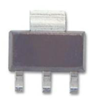
- Package Options: SOT-223, TO-92, and DFN packages
Pin Configuration and Descriptions
The LT3092 is available in multiple package types. Below is the pin configuration for the SOT-223 package:
| Pin Number | Pin Name | Description |
|---|---|---|
| 1 | SET | Connects to the resistor network to set the output current or voltage. |
| 2 | OUT | Regulated output voltage. Connect to the load. |
| 3 | IN | Input voltage. Connect to the power supply. |
| Tab | GND | Ground connection. Provides thermal dissipation and electrical grounding. |
For other package types, refer to the manufacturer's datasheet for detailed pinouts.
Usage Instructions
How to Use the LT3092 in a Circuit
Setting the Output Voltage:
The LT3092 uses an external resistor network to set the output voltage. The output voltage is determined by the following formula:
[ V_{OUT} = I_{SET} \times R_{LOAD} ]
where ( I_{SET} ) is the current set by the resistor connected to the SET pin.Basic Circuit Configuration:
- Connect the input voltage to the IN pin. Ensure the input voltage is within the specified range (3V to 40V).
- Use a resistor between the SET pin and ground to set the desired output current.
- Connect the load to the OUT pin.
Bypass Capacitors:
- Place a 1µF ceramic capacitor close to the IN pin to improve stability and reduce input noise.
- Add a 1µF capacitor at the OUT pin to ensure stable operation and reduce output noise.
Thermal Considerations:
- Ensure proper heat dissipation by connecting the GND tab to a large copper area on the PCB.
- Use a heatsink if necessary for high-power applications.
Example Circuit with Arduino UNO
The LT3092 can be used to provide a stable voltage for powering sensors or other peripherals in an Arduino-based project. Below is an example of how to use the LT3092 to supply a 5V output:
Circuit Diagram
- Input Voltage: 12V DC
- Output Voltage: 5V DC
- Resistor Values:
- ( R_{SET} = 10k\Omega )
- ( R_{LOAD} = 5k\Omega )
Arduino Code Example
// Example code to read a sensor powered by the LT3092 regulator
// The sensor is connected to the 5V output of the LT3092

const int sensorPin = A0; // Analog pin connected to the sensor output
int sensorValue = 0;      // Variable to store the sensor reading

void setup() {
  Serial.begin(9600); // Initialize serial communication at 9600 baud
}

void loop() {
  sensorValue = analogRead(sensorPin); // Read the sensor value
  float voltage = sensorValue * (5.0 / 1023.0); // Convert to voltage
  Serial.print("Sensor Voltage: ");
  Serial.print(voltage);
  Serial.println(" V");
  delay(1000); // Wait for 1 second before the next reading
}
Important Considerations and Best Practices
- Ensure the input voltage is at least 300mV higher than the desired output voltage to maintain proper regulation.
- Use low-tolerance resistors for the SET and LOAD pins to achieve precise output voltage.
- Avoid exceeding the maximum input voltage (40V) or output current (200mA) to prevent damage to the component.
- For applications requiring very low noise, use high-quality ceramic capacitors at the input and output.
Troubleshooting and FAQs
Common Issues and Solutions
| Issue | Possible Cause | Solution |
|---|---|---|
| Output voltage is unstable or noisy | Insufficient bypass capacitance at the input or output. | Add a 1µF ceramic capacitor close to the IN and OUT pins. |
| Output voltage is incorrect | Incorrect resistor values for the SET and LOAD pins. | Verify and recalculate the resistor values based on the desired output. |
| Regulator overheats during operation | Excessive power dissipation or insufficient thermal management. | Use a heatsink or improve PCB thermal design. |
| No output voltage | Input voltage is below the minimum required or the component is damaged. | Check the input voltage and ensure it is within the specified range. |
FAQs
Can the LT3092 be used for negative voltage regulation?
Yes, the LT3092 can be configured for negative voltage regulation by connecting the IN pin to ground and the OUT pin to a negative voltage source.What is the maximum output current of the LT3092?
The LT3092 can provide up to 200mA of output current.Can I use the LT3092 without a heatsink?
Yes, for low-power applications. However, for higher power dissipation, a heatsink or proper PCB thermal design is recommended.What type of capacitors should I use with the LT3092?
Use high-quality ceramic capacitors with low equivalent series resistance (ESR) for optimal performance.
By following this documentation, users can effectively integrate the LT3092 into their designs and troubleshoot common issues. For more detailed information, refer to the official datasheet provided by Analog Devices.