
How to Use VARISTOR: Examples, Pinouts, and Specs
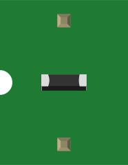
 Design with VARISTOR in Cirkit Designer
Introduction
A varistor is a voltage-dependent resistor that changes its resistance based on the applied voltage. It is primarily used to protect electronic circuits from voltage spikes and surges by clamping excess voltage to a safe level. Varistors are commonly found in power supplies, surge protectors, and electronic devices to safeguard sensitive components from transient overvoltages.
Explore Projects Built with VARISTOR
 Open Project in Cirkit Designer
 Open Project in Cirkit Designer
 Open Project in Cirkit Designer
 Open Project in Cirkit Designer
Explore Projects Built with VARISTOR
Open Project in Cirkit DesignerOpen Project in Cirkit DesignerOpen Project in Cirkit DesignerOpen Project in Cirkit DesignerCommon Applications and Use Cases
- Surge protection in power lines and electronic devices
- Voltage spike suppression in motor control circuits
- Protection of sensitive components in communication systems
- Overvoltage protection in industrial equipment
Technical Specifications
Key Technical Details
- Operating Voltage Range: Typically 5V to 1000V (varies by model)
- Clamping Voltage: The voltage at which the varistor starts conducting (e.g., 18V, 275V, etc.)
- Energy Absorption Capacity: Measured in joules (e.g., 10J, 50J, etc.)
- Response Time: Less than 25 nanoseconds
- Maximum Surge Current: Varies by model, typically in the range of 100A to 10,000A
- Capacitance: Typically in the range of 100pF to several nanofarads
Pin Configuration and Descriptions
Varistors are typically two-terminal devices with no polarity. Below is a general description of the pins:
| Pin Number | Pin Name | Description |
|---|---|---|
| 1 | Terminal 1 | Connects to one side of the circuit |
| 2 | Terminal 2 | Connects to the other side of the circuit |
Usage Instructions
How to Use the Component in a Circuit
- Identify the Voltage Rating: Select a varistor with a clamping voltage slightly higher than the normal operating voltage of your circuit.
- Placement in Circuit: Connect the varistor in parallel with the component or circuit you want to protect. This ensures that any voltage spike is diverted through the varistor.
- Polarity: Varistors are non-polarized, so they can be connected in either direction.
- Soldering: Use appropriate soldering techniques to ensure a secure connection. Avoid overheating the varistor during soldering.
Important Considerations and Best Practices
- Voltage Selection: Ensure the varistor's clamping voltage is higher than the circuit's normal operating voltage but lower than the maximum voltage the circuit can tolerate.
- Energy Rating: Choose a varistor with an energy absorption capacity suitable for the expected surge energy.
- Series Resistance: In some cases, adding a series resistor can help limit the current through the varistor during a surge.
- Temperature: Avoid exposing the varistor to high temperatures, as this can degrade its performance over time.
Example: Using a Varistor with an Arduino UNO
To protect an Arduino UNO from voltage spikes on its power supply line, you can use a varistor with a clamping voltage of around 18V. Here's how to connect it:
- Place the varistor across the Arduino's power supply terminals (VIN and GND).
- Ensure the varistor's clamping voltage is higher than the Arduino's operating voltage (5V or 12V, depending on the power source).
// Example code for Arduino UNO to demonstrate normal operation
// This code does not directly interact with the varistor but assumes
// the varistor is protecting the power supply line.

void setup() {
  pinMode(13, OUTPUT); // Set pin 13 as an output
}

void loop() {
  digitalWrite(13, HIGH); // Turn on the LED
  delay(1000);            // Wait for 1 second
  digitalWrite(13, LOW);  // Turn off the LED
  delay(1000);            // Wait for 1 second
}

// Note: The varistor will protect the Arduino from voltage spikes
// on the power supply line, ensuring stable operation.
Troubleshooting and FAQs
Common Issues Users Might Face
Varistor Fails to Protect the Circuit:
- Cause: Incorrect voltage rating or energy capacity.
- Solution: Verify the varistor's clamping voltage and energy rating. Replace with a suitable model if necessary.
Varistor Overheats or Fails:
- Cause: Repeated exposure to high-energy surges or excessive current.
- Solution: Use a varistor with a higher energy rating or add a series resistor to limit current.
Circuit Still Experiences Voltage Spikes:
- Cause: Improper placement of the varistor in the circuit.
- Solution: Ensure the varistor is connected in parallel with the component or circuit being protected.
Solutions and Tips for Troubleshooting
- Check Connections: Ensure the varistor is securely soldered and connected in the correct location.
- Inspect for Damage: Replace the varistor if it shows signs of physical damage, such as cracks or discoloration.
- Test with a Multimeter: Use a multimeter to check the varistor's resistance. A damaged varistor may show an open or short circuit.
By following these guidelines, you can effectively use a varistor to protect your electronic circuits from voltage surges and spikes.