How to Use 4023: Examples, Pinouts, and Specs
Introduction
The 4023 is a dual 4-input NAND gate integrated circuit (IC) that is widely used in digital electronics for implementing various logic functions. This versatile component features two independent NAND gates, each capable of accepting four input signals. The 4023 is ideal for applications requiring complex logic operations, such as data processing, signal conditioning, and control systems.
Explore Projects Built with 4023


Explore Projects Built with 4023
Common Applications and Use Cases
- Digital Logic Design: Used in combinational logic circuits.
- Signal Processing: Employed in filtering and signal conditioning applications.
- Control Systems: Utilized in automation and control logic.
- Data Communication: Functions in encoding and decoding logic.
Technical Specifications
Key Technical Details
| Parameter | Value |
|---|---|
| Supply Voltage (Vcc) | 3V to 15V |
| Input Voltage (Vi) | 0V to Vcc |
| Output Voltage (Vo) | 0V to Vcc |
| Maximum Output Current | 25 mA |
| Power Dissipation | 500 mW |
| Operating Temperature | -55°C to +125°C |
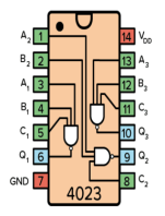
Pin Configuration and Descriptions
| Pin Number | Pin Name | Description |
|---|---|---|
| 1 | A1 | Input 1 for NAND Gate 1 |
| 2 | A2 | Input 2 for NAND Gate 1 |
| 3 | A3 | Input 3 for NAND Gate 1 |
| 4 | A4 | Input 4 for NAND Gate 1 |
| 5 | Y1 | Output for NAND Gate 1 |
| 6 | GND | Ground connection |
| 7 | Vcc | Supply voltage connection |
| 8 | A5 | Input 1 for NAND Gate 2 |
| 9 | A6 | Input 2 for NAND Gate 2 |
| 10 | A7 | Input 3 for NAND Gate 2 |
| 11 | A8 | Input 4 for NAND Gate 2 |
| 12 | Y2 | Output for NAND Gate 2 |
Usage Instructions
How to Use the Component in a Circuit
- Power Supply Connection: Connect the Vcc pin (Pin 7) to the positive supply voltage and the GND pin (Pin 6) to ground.
- Input Connections: Connect your input signals to the appropriate input pins (A1 to A4 for NAND Gate 1 and A5 to A8 for NAND Gate 2).
- Output Connection: Connect the output pins (Y1 for NAND Gate 1 and Y2 for NAND Gate 2) to the next stage of your circuit.
Important Considerations and Best Practices
- Ensure that the supply voltage does not exceed the maximum rating of 15V.
- Avoid connecting inputs directly to the supply voltage or ground without a resistor to prevent damage.
- Use pull-up or pull-down resistors if necessary to ensure stable logic levels.
- Keep the operating temperature within the specified range to maintain performance.
Troubleshooting and FAQs
Common Issues Users Might Face
No Output Signal:
- Solution: Check the power supply connections and ensure that the Vcc and GND pins are properly connected.
Unexpected Output Levels:
- Solution: Verify that all input signals are within the specified voltage range. Check for floating inputs.
Overheating:
- Solution: Ensure that the IC is not subjected to excessive current. Check for short circuits in the circuit.
Tips for Troubleshooting
- Use a multimeter to measure voltage levels at the input and output pins.
- If using in a breadboard setup, ensure all connections are secure and not loose.
- Consult the datasheet for additional specifications and characteristics.
Example Code for Arduino UNO
If you are using the 4023 NAND gate with an Arduino UNO, here is a simple example code to demonstrate how to read inputs and control outputs based on the NAND logic.
// Define pin numbers for inputs and output
const int input1 = 2; // A1
const int input2 = 3; // A2
const int output1 = 4; // Y1

void setup() {
  // Initialize input pins
  pinMode(input1, INPUT);
  pinMode(input2, INPUT);

  // Initialize output pin
  pinMode(output1, OUTPUT);
}

void loop() {
  // Read input values
  int val1 = digitalRead(input1);
  int val2 = digitalRead(input2);

  // Implement NAND logic
  int outputValue = !(val1 && val2);

  // Set output pin based on NAND logic
  digitalWrite(output1, outputValue);

  // Small delay for stability
  delay(100);
}
This code reads two input signals and produces an output based on the NAND logic. Make sure to connect the input pins to the corresponding pins on the 4023 IC.