How to Use EC200U LTE 4G GNSS: Examples, Pinouts, and Specs
Introduction
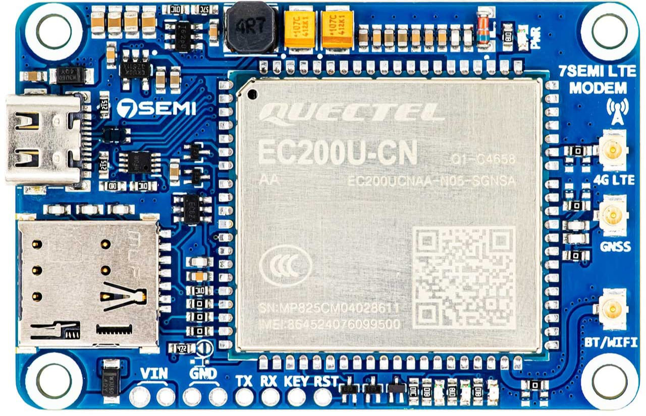
The EC200U, manufactured by Uno (Part ID: Uno), is a compact LTE module designed to provide reliable 4G connectivity and GNSS (Global Navigation Satellite System) capabilities. This versatile module is ideal for IoT applications that require high-speed data transmission and precise location tracking. Its small form factor and robust performance make it suitable for a wide range of use cases, including smart transportation, asset tracking, industrial automation, and remote monitoring.
Explore Projects Built with EC200U LTE 4G GNSS
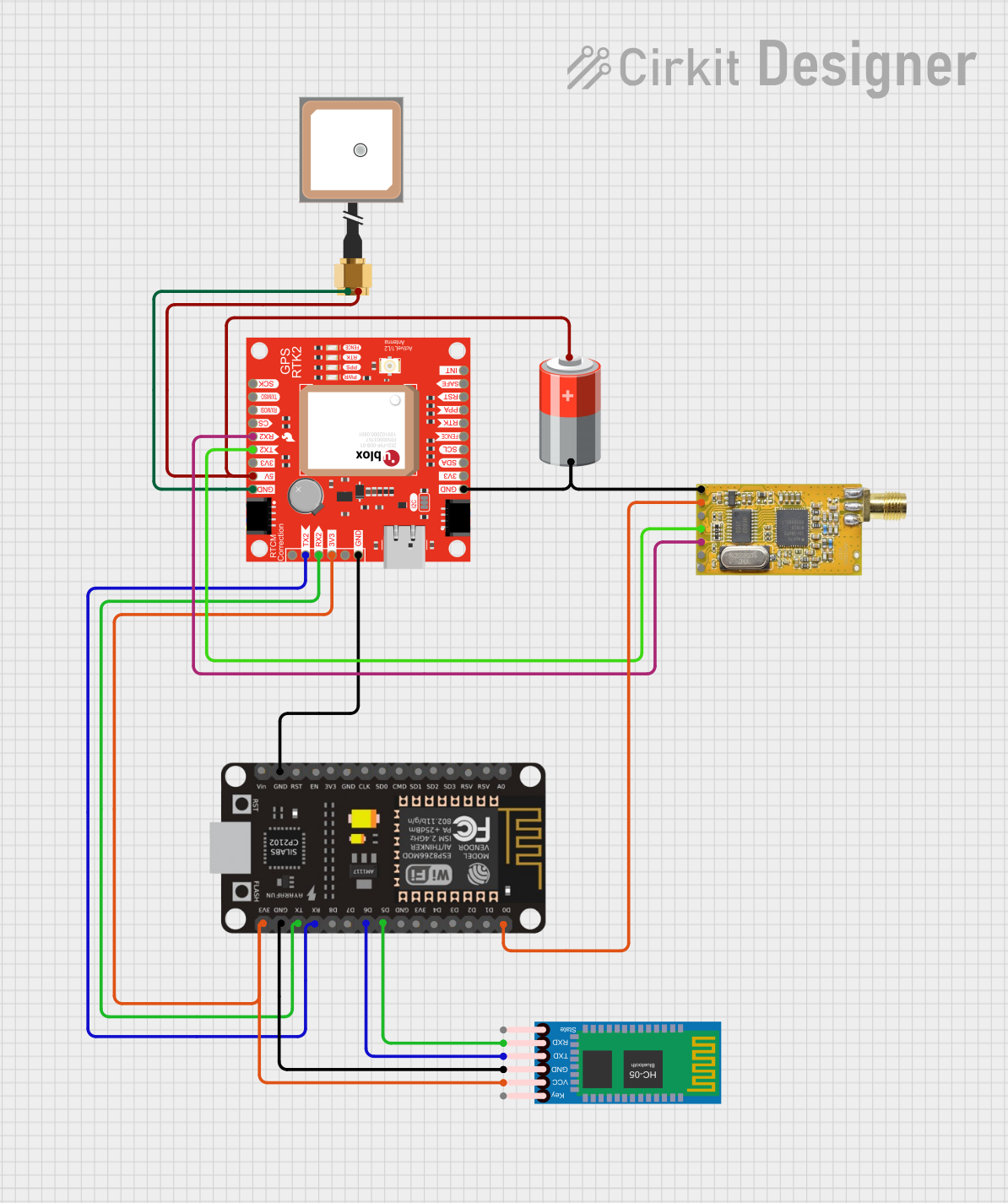


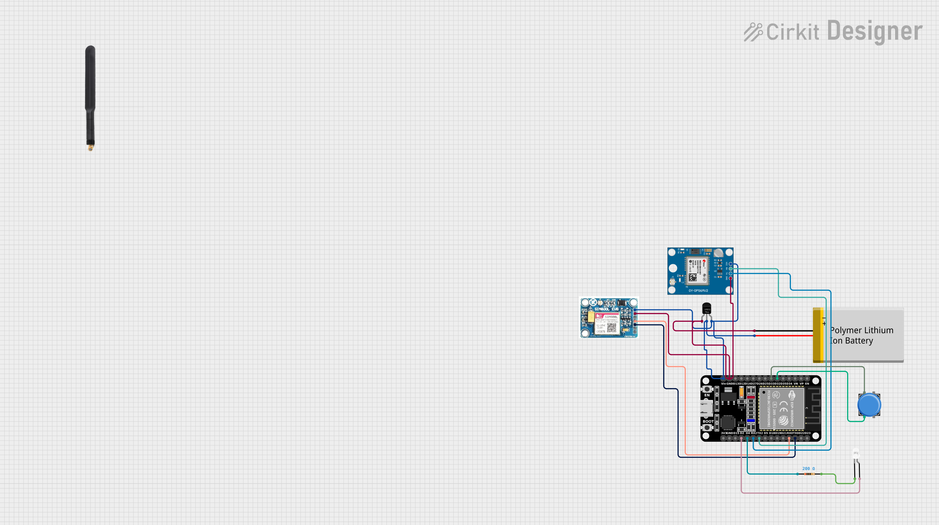
Explore Projects Built with EC200U LTE 4G GNSS
Common Applications
- Smart Transportation: Real-time vehicle tracking and fleet management.
- Asset Tracking: Monitoring the location and status of valuable assets.
- Industrial Automation: Enabling remote control and monitoring of industrial equipment.
- Remote Monitoring: Collecting and transmitting data from remote sensors or devices.
- IoT Devices: Supporting high-speed data communication for connected devices.
Technical Specifications
Key Technical Details
| Parameter | Specification |
|---|---|
| Manufacturer | Uno |
| Part ID | Uno |
| Cellular Connectivity | LTE (4G) |
| GNSS Support | GPS, GLONASS, BeiDou, Galileo |
| Operating Voltage | 3.3V - 4.3V |
| Power Consumption | Idle: ~1.5mA, Active: ~500mA (typical, depending on network conditions) |
| Data Rate | Up to 150 Mbps (downlink), 50 Mbps (uplink) |
| Operating Temperature | -40°C to +85°C |
| Dimensions | 29.0mm x 32.0mm x 2.4mm |
| Interface | UART, USB, GPIO, I2C, SPI |
| Antenna Interface | Supports external LTE and GNSS antennas |
Pin Configuration and Descriptions
| Pin Number | Pin Name | Description |
|---|---|---|
| 1 | VCC | Power supply input (3.3V - 4.3V) |
| 2 | GND | Ground |
| 3 | TXD | UART Transmit Data |
| 4 | RXD | UART Receive Data |
| 5 | GNSS_TXD | GNSS UART Transmit Data |
| 6 | GNSS_RXD | GNSS UART Receive Data |
| 7 | USB_D+ | USB Data Positive |
| 8 | USB_D- | USB Data Negative |
| 9 | RESET | Module Reset (Active Low) |
| 10 | PWRKEY | Power Key (used to turn the module on/off) |
| 11 | ANT_LTE | LTE Antenna Interface |
| 12 | ANT_GNSS | GNSS Antenna Interface |
Usage Instructions
How to Use the EC200U in a Circuit
- Power Supply: Connect the VCC pin to a stable power source (3.3V - 4.3V) and GND to ground.
- UART Communication: Use the TXD and RXD pins to interface with a microcontroller or PC for data communication.
- GNSS Functionality: Connect the GNSS_TXD and GNSS_RXD pins to a UART interface for GNSS data output.
- Antenna Connections: Attach external LTE and GNSS antennas to the ANT_LTE and ANT_GNSS pins, respectively, for optimal signal reception.
- Power Control: Use the PWRKEY pin to turn the module on or off. Pull the pin low for at least 1 second to power on the module.
- Reset: If needed, use the RESET pin to restart the module by pulling it low momentarily.
Important Considerations
- Ensure the power supply is stable and within the specified voltage range to avoid damage to the module.
- Use high-quality antennas to maximize LTE and GNSS performance.
- Place the module away from sources of electromagnetic interference (EMI) for reliable operation.
- For UART communication, ensure the baud rate matches the module's default setting (typically 115200 bps).
Example: Connecting EC200U to Arduino UNO
Below is an example of how to interface the EC200U with an Arduino UNO for basic communication:
Circuit Connections
| EC200U Pin | Arduino UNO Pin |
|---|---|
| VCC | 3.3V |
| GND | GND |
| TXD | Pin 10 (RX) |
| RXD | Pin 11 (TX) |
| PWRKEY | Digital Pin 7 |
Arduino Code
#include <SoftwareSerial.h>

// Define software serial pins for EC200U communication
SoftwareSerial ec200uSerial(10, 11); // RX = Pin 10, TX = Pin 11

#define PWRKEY 7 // Power key pin

void setup() {
  // Initialize serial communication
  Serial.begin(115200); // For debugging
  ec200uSerial.begin(115200); // Communication with EC200U

  // Configure PWRKEY pin
  pinMode(PWRKEY, OUTPUT);
  digitalWrite(PWRKEY, HIGH); // Set PWRKEY to HIGH initially

  // Power on the EC200U module
  Serial.println("Powering on EC200U...");
  digitalWrite(PWRKEY, LOW); // Pull PWRKEY low
  delay(1000); // Hold for 1 second
  digitalWrite(PWRKEY, HIGH); // Release PWRKEY
  delay(5000); // Wait for the module to initialize
  Serial.println("EC200U powered on.");
}

void loop() {
  // Check for data from EC200U
  if (ec200uSerial.available()) {
    String data = ec200uSerial.readString();
    Serial.println("Data from EC200U: " + data);
  }

  // Send data to EC200U
  if (Serial.available()) {
    String command = Serial.readString();
    ec200uSerial.println(command);
    Serial.println("Command sent to EC200U: " + command);
  }
}
Troubleshooting and FAQs
Common Issues and Solutions
Module Not Powering On
- Ensure the power supply voltage is within the specified range (3.3V - 4.3V).
- Verify the PWRKEY pin is being pulled low for at least 1 second during power-on.
No Response from Module
- Check the UART connections (TXD and RXD) and ensure they are not swapped.
- Confirm the baud rate matches the module's default setting (115200 bps).
Poor GNSS Signal
- Ensure the GNSS antenna is placed in an open area with a clear view of the sky.
- Avoid placing the module near sources of interference, such as power supplies or motors.
LTE Connectivity Issues
- Verify the SIM card is properly inserted and activated.
- Check the LTE antenna connection and ensure it is securely attached.
FAQs
Q: Can the EC200U operate on 2G or 3G networks?
A: No, the EC200U is designed specifically for LTE (4G) networks.Q: What is the default baud rate for UART communication?
A: The default baud rate is 115200 bps.Q: Does the module support SMS functionality?
A: Yes, the EC200U supports SMS sending and receiving via AT commands.Q: Can I use the EC200U with a 5V microcontroller?
A: Yes, but you must use a level shifter to convert the 5V signals to 3.3V for the EC200U.
This concludes the documentation for the EC200U LTE 4G GNSS module.