How to Use Timer Relay Programmable: Examples, Pinouts, and Specs
Introduction
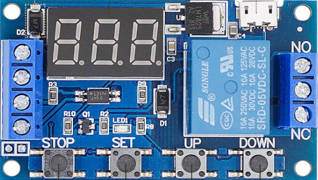
The Valefod Timer Relay Programmable is an electromechanical device designed to control the timing of electrical circuits. It allows users to set precise time delays for turning circuits on or off, enabling automation in a wide range of applications. This component is highly versatile and can be programmed for various timing functions, making it ideal for use in lighting systems, HVAC systems, industrial machinery, and other automated processes.
Explore Projects Built with Timer Relay Programmable

Explore Projects Built with Timer Relay Programmable
Common Applications and Use Cases
- Lighting Automation: Automatically turn lights on or off after a set time.
- HVAC Systems: Control heating, ventilation, and air conditioning equipment based on timing schedules.
- Industrial Machinery: Manage the operation of machines with precise time delays.
- Irrigation Systems: Automate watering schedules for agricultural or landscaping purposes.
- Home Automation: Integrate into smart home systems for enhanced control and energy efficiency.
Technical Specifications
Key Technical Details
| Parameter | Value |
|---|---|
| Operating Voltage | 6V to 30V DC |
| Maximum Load Current | 10A |
| Timing Range | 0.1 seconds to 999 minutes |
| Display Type | LED digital display |
| Control Modes | Multiple programmable modes (e.g., delay on, delay off) |
| Power Consumption | < 0.1W |
| Operating Temperature | -40°C to 85°C |
| Dimensions | 60mm x 34mm x 12mm |
Pin Configuration and Descriptions
| Pin Name | Description |
|---|---|
| VCC | Positive power supply input (6V to 30V DC). |
| GND | Ground connection for the power supply. |
| IN+ | Positive input for the load or external trigger signal. |
| IN- | Negative input for the load or external trigger signal. |
| NO | Normally Open terminal for the relay. Connect to the load for switching. |
| COM | Common terminal for the relay. Connect to the power source or load. |
| NC | Normally Closed terminal for the relay. Use for circuits requiring default ON. |
Usage Instructions
How to Use the Component in a Circuit
- Power the Timer Relay: Connect the VCC pin to a DC power source (6V to 30V) and the GND pin to ground.
- Connect the Load:
- For a normally open configuration, connect the load between the NO and COM pins.
- For a normally closed configuration, connect the load between the NC and COM pins.
- Set the Timing Parameters:
- Use the onboard buttons to program the desired delay time and mode of operation.
- Refer to the LED display for real-time feedback on the settings.
- Trigger the Relay:
- Apply a signal to the IN+ and IN- pins to activate the relay based on the programmed timing.
Important Considerations and Best Practices
- Voltage Compatibility: Ensure the power supply voltage matches the operating range (6V to 30V DC).
- Load Ratings: Do not exceed the maximum load current of 10A to avoid damaging the relay.
- Heat Dissipation: If operating at high currents, ensure proper ventilation or heat dissipation to prevent overheating.
- Debouncing: For external triggers, use a debouncing circuit to avoid false triggering.
- Safety: Always disconnect the power supply before wiring or modifying the circuit.
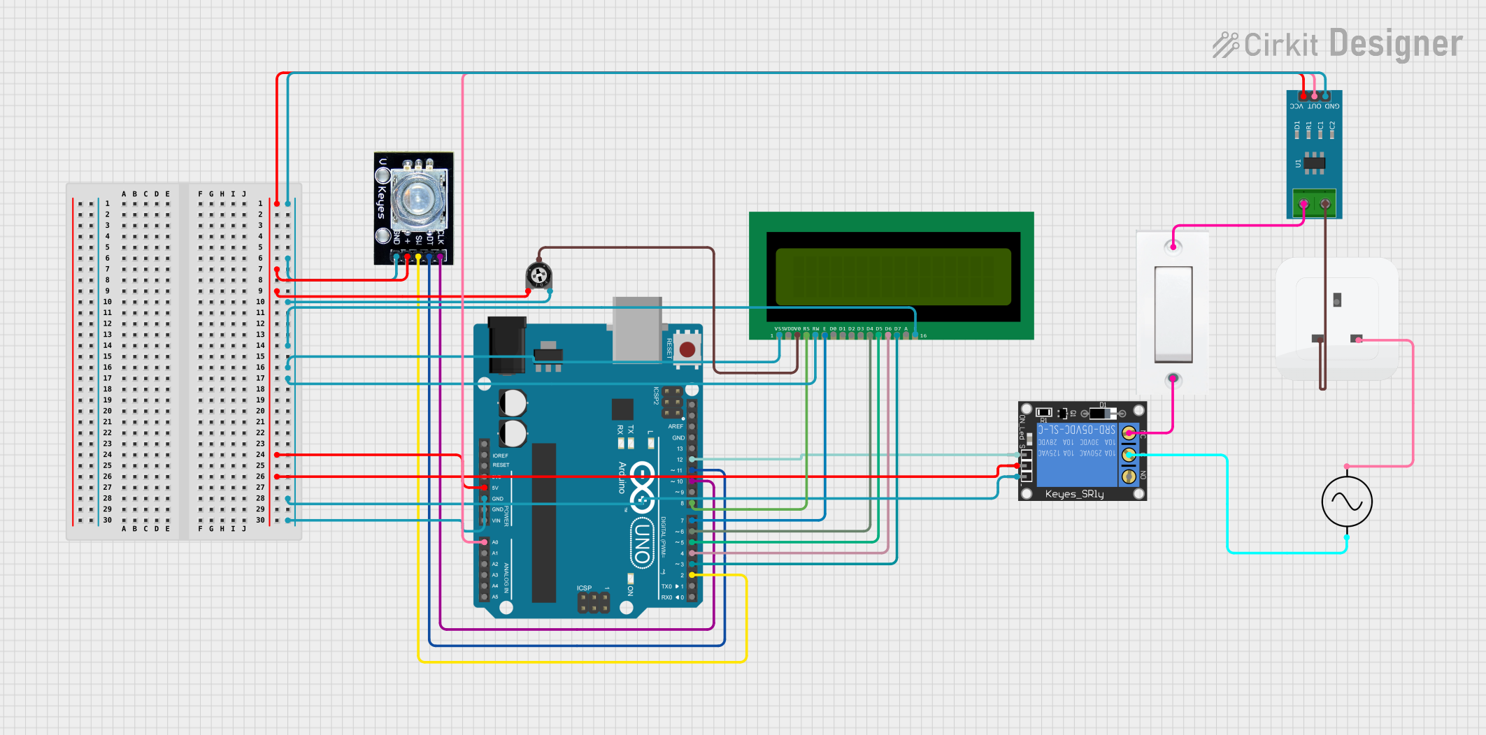
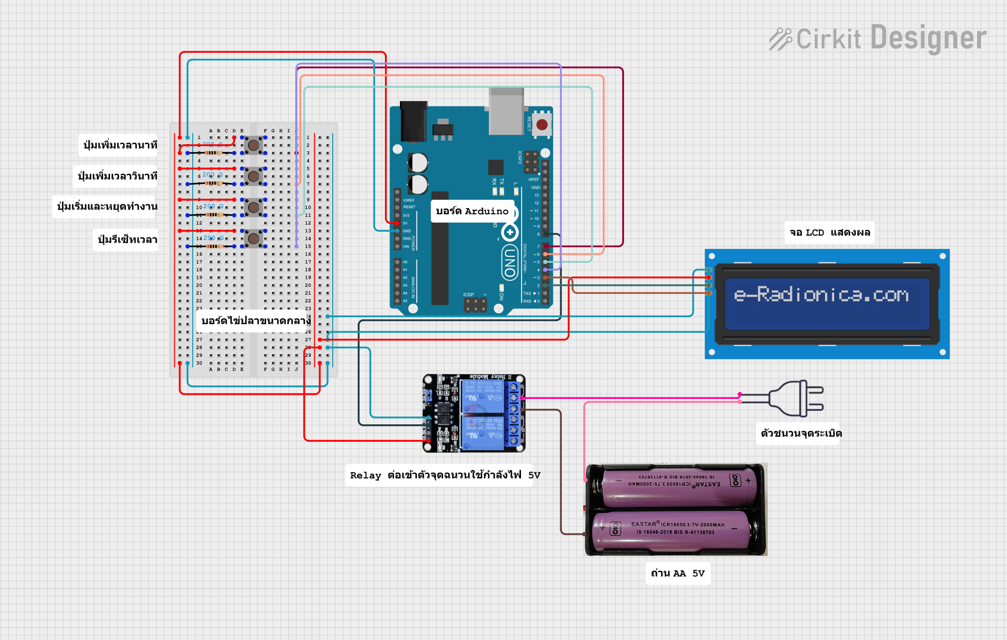
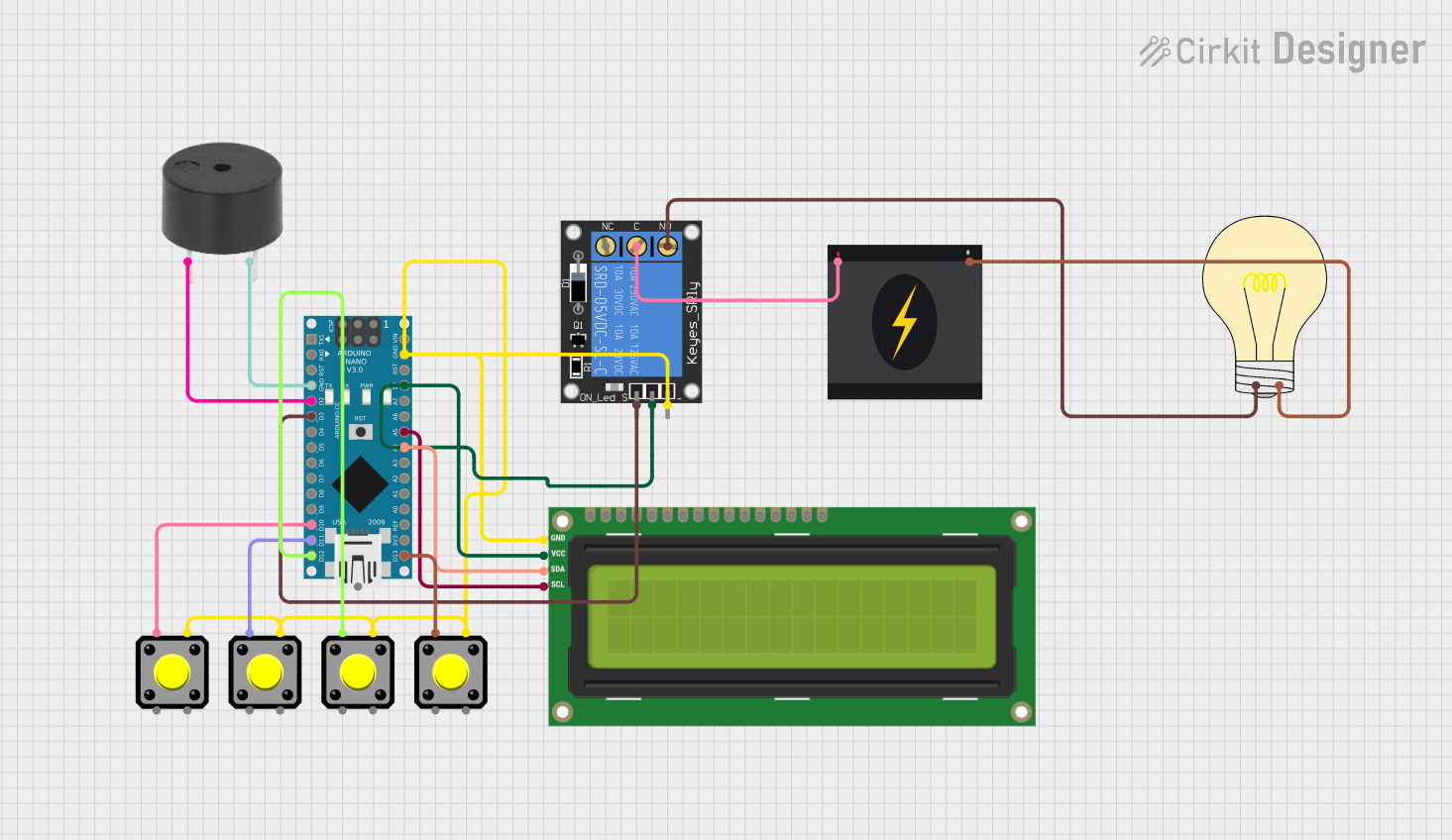
Example: Using with Arduino UNO
The Valefod Timer Relay Programmable can be easily integrated with an Arduino UNO for advanced automation. Below is an example code to control the relay:
// Example: Controlling the Timer Relay with Arduino UNO
// Connect IN+ to Arduino pin 7 and IN- to GND

#define RELAY_PIN 7  // Define the pin connected to the relay's IN+ terminal

void setup() {
  pinMode(RELAY_PIN, OUTPUT);  // Set the relay pin as an output
  digitalWrite(RELAY_PIN, LOW); // Ensure the relay is off initially
}

void loop() {
  digitalWrite(RELAY_PIN, HIGH); // Turn the relay ON
  delay(5000);                   // Wait for 5 seconds
  digitalWrite(RELAY_PIN, LOW);  // Turn the relay OFF
  delay(5000);                   // Wait for 5 seconds
}
Troubleshooting and FAQs
Common Issues and Solutions
| Issue | Possible Cause | Solution |
|---|---|---|
| Relay does not activate | Incorrect wiring or insufficient power | Verify all connections and ensure the power supply is within the operating range. |
| Timing is inaccurate | Incorrect programming of delay parameters | Reprogram the timing settings and confirm using the LED display. |
| Relay overheats | Load exceeds maximum current rating | Reduce the load or use an external relay for higher current applications. |
| LED display not working | Faulty power supply or damaged component | Check the power supply and inspect the relay for physical damage. |
| External trigger not functioning | Signal not reaching IN+ and IN- pins | Verify the trigger signal and ensure proper connection to the input pins. |
FAQs
Can this relay be used with AC loads?
- Yes, but ensure the AC load does not exceed the relay's maximum current rating (10A).
What happens if the power supply is interrupted?
- The relay will reset, and the timing program will need to be reconfigured unless a backup power source is used.
Can I use this relay for PWM signals?
- No, this relay is not designed for high-frequency switching and is unsuitable for PWM applications.
How do I reset the relay to factory settings?
- Press and hold the programming button for 5 seconds until the LED display resets.
Is the relay waterproof?
- No, the relay is not waterproof. Use it in a dry environment or within a protective enclosure.
This documentation provides a comprehensive guide to using the Valefod Timer Relay Programmable effectively. For further assistance, refer to the manufacturer's user manual or contact technical support.