
How to Use INFINEON_KIT_XMC47_RELAX_V1: Examples, Pinouts, and Specs
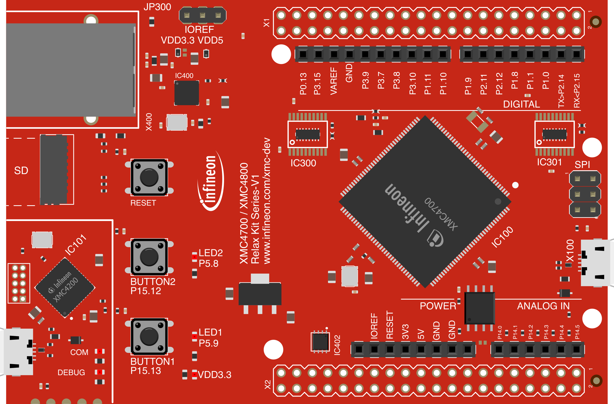
 Design with INFINEON_KIT_XMC47_RELAX_V1 in Cirkit Designer
Introduction
The INFINEON_KIT_XMC47_RELAX_V1 (Manufacturer Part ID: KITXMC47RELAXV1TOBO1) is a development kit designed by Infineon Technologies. It features the XMC4700 microcontroller, a high-performance ARM® Cortex®-M4-based MCU optimized for industrial and IoT applications. This kit is tailored for rapid prototyping and evaluation of embedded systems, offering a wide range of interfaces and peripherals for seamless integration into various applications.
Explore Projects Built with INFINEON_KIT_XMC47_RELAX_V1
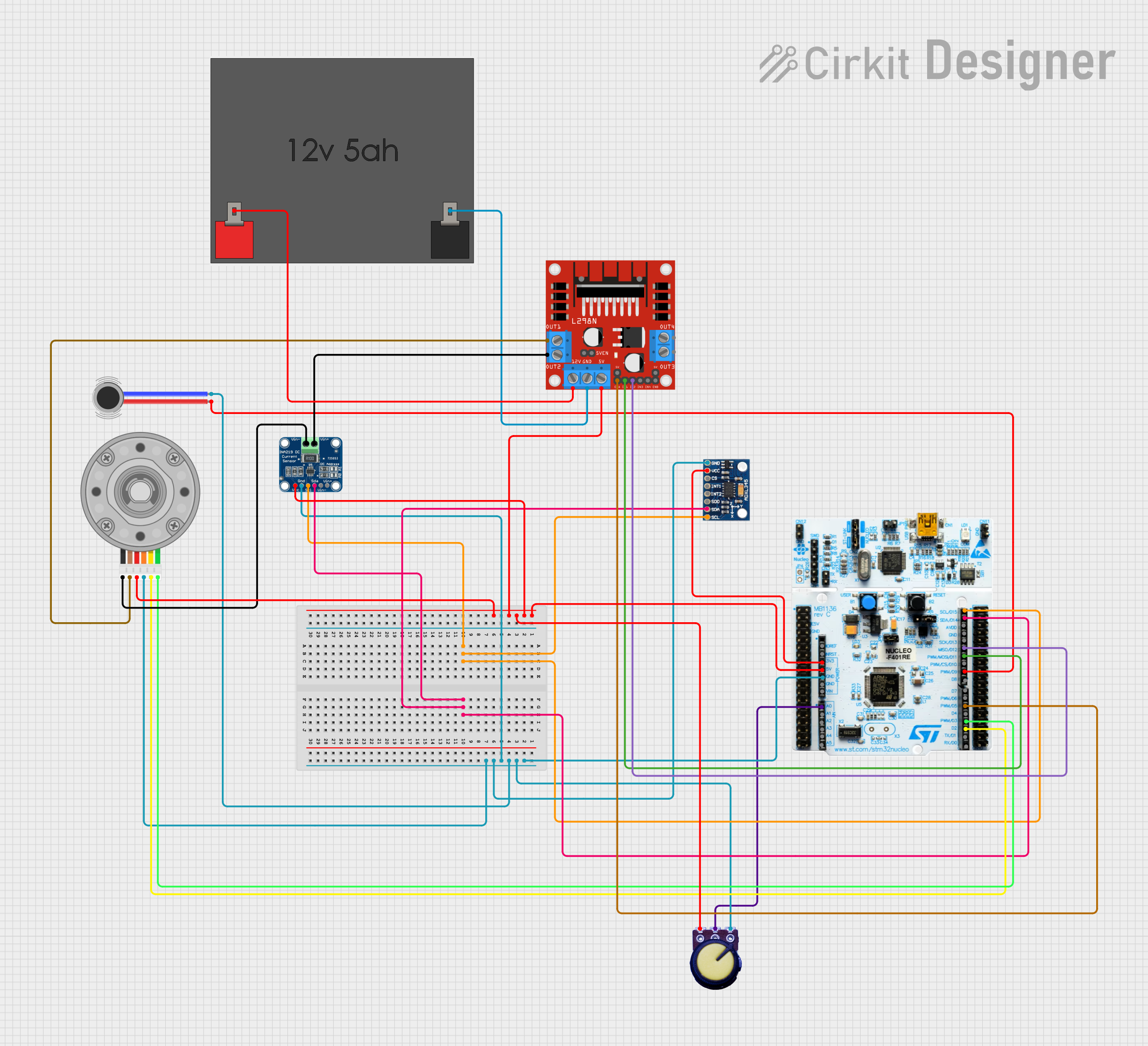 Open Project in Cirkit Designer
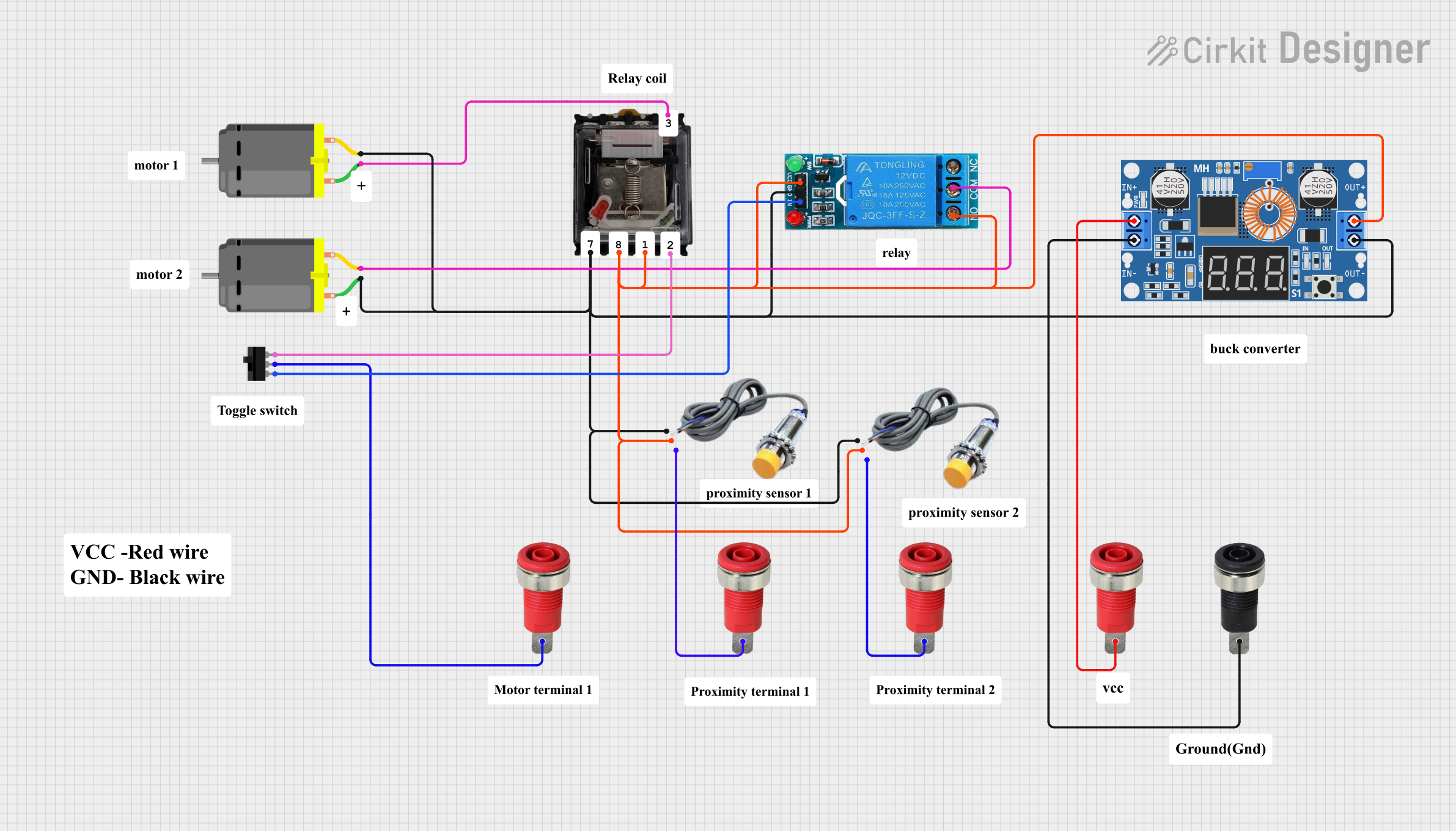 Open Project in Cirkit Designer
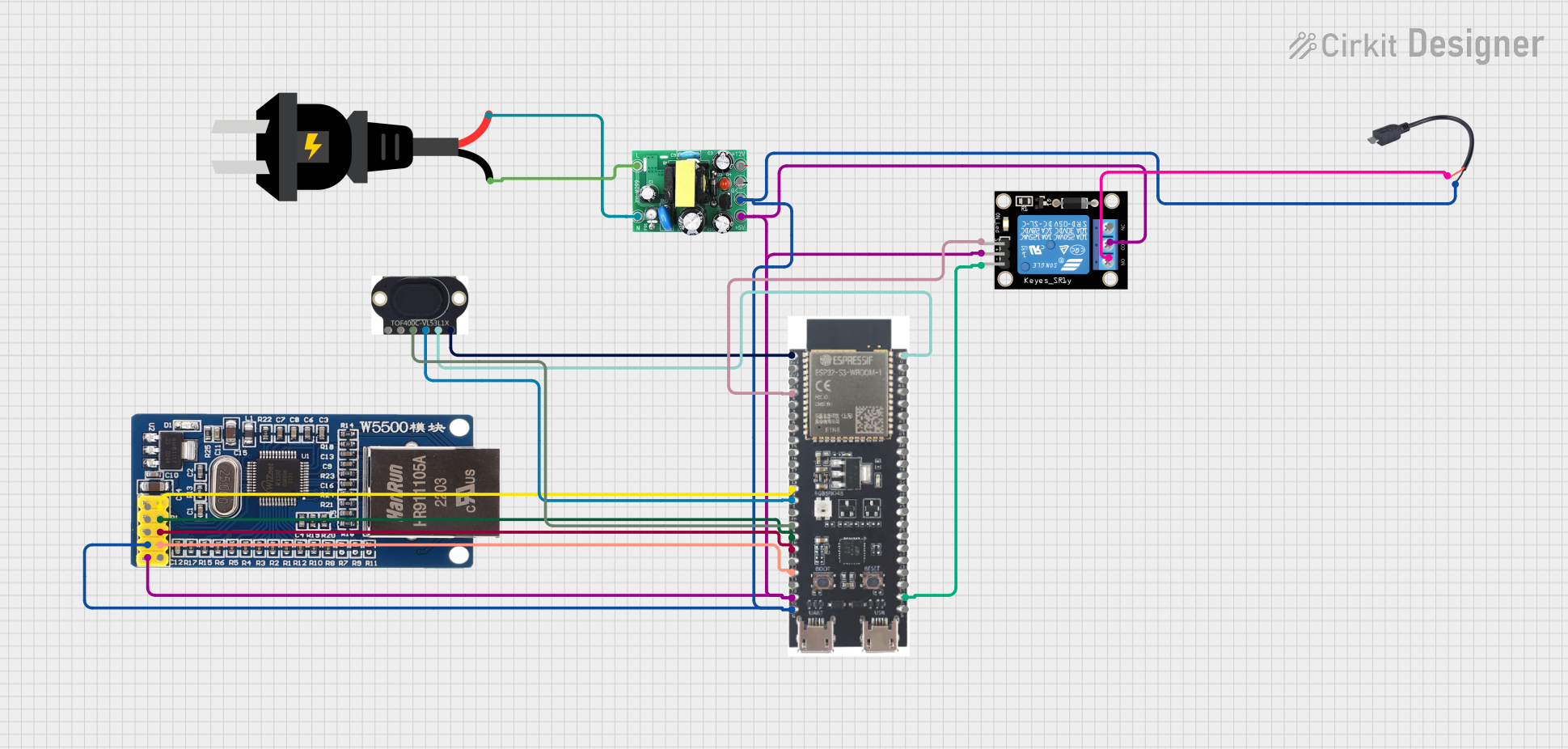 Open Project in Cirkit Designer
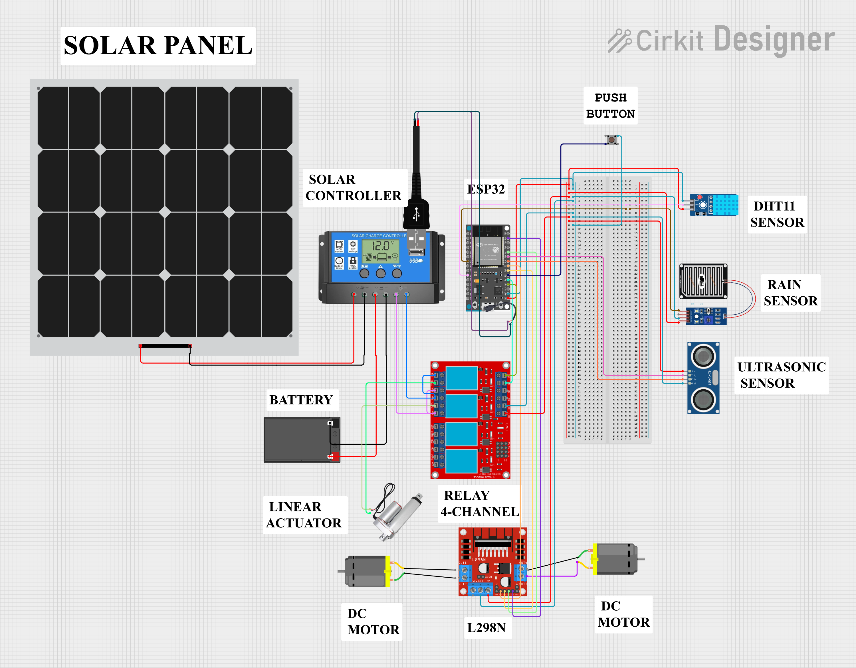 Open Project in Cirkit Designer
Explore Projects Built with INFINEON_KIT_XMC47_RELAX_V1
Open Project in Cirkit DesignerOpen Project in Cirkit DesignerOpen Project in Cirkit DesignerOpen Project in Cirkit DesignerCommon Applications and Use Cases
- Industrial automation and control systems
- IoT edge devices and gateways
- Motor control and power conversion
- Smart home and building automation
- Prototyping for embedded systems with Ethernet and USB connectivity
Technical Specifications
Key Technical Details
| Parameter | Specification |
|---|---|
| Microcontroller | XMC4700 (ARM® Cortex®-M4, 144 MHz) |
| Flash Memory | 2 MB |
| RAM | 352 KB |
| Operating Voltage | 3.3 V |
| Debug Interface | On-board J-Link Lite Debugger |
| Communication Interfaces | Ethernet, USB, UART, SPI, I2C, CAN |
| GPIO Pins | Multiple configurable GPIOs |
| Power Supply | USB-powered (5 V) |
| Dimensions | 100 mm x 50 mm |
Pin Configuration and Descriptions
The INFINEON_KIT_XMC47_RELAX_V1 provides access to various pins via headers. Below is a summary of the key pin configurations:
GPIO Header Pinout
| Pin Number | Pin Name | Functionality | Notes |
|---|---|---|---|
| 1 | VDD | 3.3 V Power Supply | Power for external components |
| 2 | GND | Ground | Common ground |
| 3 | P0.0 | GPIO / UART_TXD | Configurable as UART TX |
| 4 | P0.1 | GPIO / UART_RXD | Configurable as UART RX |
| 5 | P1.0 | GPIO / PWM Output | Configurable as PWM |
| 6 | P1.1 | GPIO / ADC Input | Configurable as ADC |
| ... | ... | ... | ... |
Communication Interfaces
| Interface | Pins Used | Description |
|---|---|---|
| Ethernet | TX+, TX-, RX+, RX- | Supports 10/100 Mbps Ethernet communication |
| USB | D+, D- | USB 2.0 Full-Speed Device |
| CAN | CAN_H, CAN_L | CAN bus communication |
| I2C | SDA, SCL | I2C communication |
| SPI | MOSI, MISO, SCK | SPI communication |
Usage Instructions
How to Use the Component in a Circuit
Powering the Board:
- Connect the board to a PC or USB power source using a micro-USB cable. The board operates at 5 V via USB and regulates it to 3.3 V internally.
Programming the Microcontroller:
- Use the on-board J-Link Lite Debugger to program the XMC4700 microcontroller. Compatible IDEs include Infineon DAVE and Keil µVision.
Connecting Peripherals:
- Use the GPIO headers to connect external sensors, actuators, or other peripherals. Ensure the voltage levels are compatible with the 3.3 V logic of the board.
Ethernet and USB Communication:
- For Ethernet-based applications, connect the board to a network using the RJ45 Ethernet port.
- For USB communication, connect the board to a PC and configure the USB interface as needed.
Flashing Firmware:
- Open the Infineon DAVE IDE, write or import your application code, and flash it to the XMC4700 using the J-Link debugger.
Important Considerations and Best Practices
- Voltage Levels: Ensure all external components connected to the GPIO pins operate at 3.3 V logic levels to avoid damage.
- Debugging: Use the on-board J-Link Lite Debugger for efficient debugging and firmware updates.
- Static Protection: Handle the board with care to avoid electrostatic discharge (ESD) damage.
- Clock Configuration: Configure the system clock appropriately in your firmware to ensure proper operation of peripherals.
Example Code for Arduino UNO Integration
Although the XMC4700 is not directly compatible with Arduino, it can communicate with an Arduino UNO via UART. Below is an example of how to send data from the XMC4700 to an Arduino UNO:
Arduino UNO Code
// Arduino UNO: Receive data from XMC4700 via UART
void setup() {
  Serial.begin(9600); // Initialize UART at 9600 baud rate
}

void loop() {
  if (Serial.available() > 0) {
    char receivedChar = Serial.read(); // Read incoming data
    Serial.print("Received: ");
    Serial.println(receivedChar); // Print received data
  }
}
XMC4700 Code (Pseudocode)
#include <xmc_uart.h>

// Configure UART for XMC4700
void UART_Init() {
  XMC_UART_CH_CONFIG_t uart_config = {
    .baudrate = 9600, // Set baud rate to 9600
    .data_bits = 8,
    .stop_bits = 1,
    .parity_mode = XMC_USIC_CH_PARITY_MODE_NONE
  };

  XMC_UART_CH_Init(XMC_UART0_CH0, &uart_config); // Initialize UART channel
  XMC_UART_CH_Start(XMC_UART0_CH0); // Start UART communication
}

void UART_SendChar(char c) {
  while (XMC_USIC_CH_GetTransmitBufferStatus(XMC_UART0_CH0) == 0); // Wait for buffer
  XMC_UART_CH_Transmit(XMC_UART0_CH0, c); // Transmit character
}

int main() {
  UART_Init(); // Initialize UART
  while (1) {
    UART_SendChar('A'); // Send character 'A' repeatedly
    XMC_Delay(1000); // Delay for 1 second
  }
}
Troubleshooting and FAQs
Common Issues Users Might Face
Board Not Powering On:
- Ensure the USB cable is properly connected and functional.
- Verify the power source provides sufficient current (at least 500 mA).
Unable to Program the Microcontroller:
- Check the connection between the board and the PC.
- Ensure the correct debugger driver is installed (e.g., J-Link driver).
- Verify the IDE settings match the XMC4700 microcontroller.
Ethernet Not Working:
- Confirm the Ethernet cable is securely connected.
- Check the network configuration (IP address, subnet mask, etc.) in your firmware.
GPIO Pins Not Responding:
- Verify the pin configuration in your firmware.
- Ensure external components are properly connected and powered.
Solutions and Tips for Troubleshooting
- Use a multimeter to check voltage levels on the board and connected peripherals.
- Update the firmware of the J-Link debugger if programming issues persist.
- Refer to the XMC4700 datasheet and Infineon DAVE documentation for detailed configuration guidance.