
How to Use DSEG8600: Examples, Pinouts, and Specs
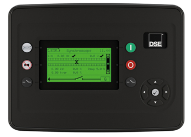
 Design with DSEG8600 in Cirkit Designer
Introduction
The DSEG8600 is a 7-segment display driver IC manufactured by Deep Sea Electronics (Part ID: G8600). This versatile component is designed to convert binary-coded decimal (BCD) inputs into the corresponding segment outputs, enabling seamless control of multiple 7-segment displays. It simplifies the process of displaying numerical information in a wide range of electronic devices.
Explore Projects Built with DSEG8600
 Open Project in Cirkit Designer
 Open Project in Cirkit Designer
 Open Project in Cirkit Designer
 Open Project in Cirkit Designer
Explore Projects Built with DSEG8600
Open Project in Cirkit DesignerOpen Project in Cirkit DesignerOpen Project in Cirkit DesignerOpen Project in Cirkit DesignerCommon Applications and Use Cases
- Digital clocks and timers
- Electronic meters and counters
- Home appliances with numerical displays
- Industrial control panels
- Educational and hobbyist projects
Technical Specifications
The DSEG8600 is optimized for efficient and reliable operation in various applications. Below are its key technical details:
Key Technical Details
| Parameter | Value |
|---|---|
| Supply Voltage (Vcc) | 4.5V to 5.5V |
| Input Voltage (Logic) | 0V to Vcc |
| Output Voltage (Segments) | 0V to Vcc |
| Maximum Output Current | 20mA per segment |
| Operating Temperature | -40°C to +85°C |
| Package Type | 16-pin DIP or SOIC |
Pin Configuration and Descriptions
The DSEG8600 features a 16-pin configuration, as detailed below:
| Pin Number | Pin Name | Description |
|---|---|---|
| 1 | A | Segment A output |
| 2 | B | Segment B output |
| 3 | C | Segment C output |
| 4 | D | Segment D output |
| 5 | E | Segment E output |
| 6 | F | Segment F output |
| 7 | G | Segment G output |
| 8 | DP | Decimal point output |
| 9 | GND | Ground |
| 10 | Vcc | Power supply (4.5V to 5.5V) |
| 11 | BCD A | BCD input bit A |
| 12 | BCD B | BCD input bit B |
| 13 | BCD C | BCD input bit C |
| 14 | BCD D | BCD input bit D |
| 15 | Enable | Enable input (active high) |
| 16 | Blank | Blanking input (active high, turns off display) |
Usage Instructions
The DSEG8600 is straightforward to use in circuits for driving 7-segment displays. Below are the steps and best practices for integrating this component into your design.
How to Use the Component in a Circuit
- Power Supply: Connect the Vcc pin (Pin 10) to a regulated 5V power supply and the GND pin (Pin 9) to ground.
- BCD Inputs: Provide a 4-bit binary-coded decimal (BCD) input to pins 11 (A), 12 (B), 13 (C), and 14 (D). These inputs determine the digit to be displayed.
- Enable and Blanking:
- Use the Enable pin (Pin 15) to activate the IC. Set it high to enable the display.
- Use the Blank pin (Pin 16) to turn off the display when needed. Set it high to blank the display.
- Segment Outputs: Connect the segment output pins (A to G and DP) to the corresponding segments of the 7-segment display. Use current-limiting resistors (e.g., 330Ω) to protect the LEDs in the display.
- Decimal Point: If the decimal point is required, connect the DP pin (Pin 8) to the decimal point segment of the display.
Important Considerations and Best Practices
- Current Limiting: Always use resistors in series with the segment outputs to limit current and prevent damage to the LEDs.
- Input Logic Levels: Ensure that the BCD inputs are within the specified voltage range (0V to Vcc).
- Decoupling Capacitor: Place a 0.1µF ceramic capacitor close to the Vcc and GND pins to reduce noise and improve stability.
- Unused Pins: If the Enable or Blank pins are not used, connect them to GND to avoid floating inputs.
Example: Connecting to an Arduino UNO
The DSEG8600 can be easily interfaced with an Arduino UNO to display numbers on a 7-segment display. Below is an example code snippet:
// Arduino example for controlling the DSEG8600 7-segment display driver

// Define BCD input pins connected to Arduino
const int bcdA = 2; // BCD A input
const int bcdB = 3; // BCD B input
const int bcdC = 4; // BCD C input
const int bcdD = 5; // BCD D input

// Define control pins
const int enablePin = 6; // Enable pin
const int blankPin = 7;  // Blank pin

void setup() {
  // Set BCD pins as outputs
  pinMode(bcdA, OUTPUT);
  pinMode(bcdB, OUTPUT);
  pinMode(bcdC, OUTPUT);
  pinMode(bcdD, OUTPUT);

  // Set control pins as outputs
  pinMode(enablePin, OUTPUT);
  pinMode(blankPin, OUTPUT);

  // Enable the display and unblank it
  digitalWrite(enablePin, HIGH); // Enable the IC
  digitalWrite(blankPin, LOW);  // Ensure display is not blanked
}

void loop() {
  // Example: Display the number 5
  digitalWrite(bcdA, LOW);  // BCD A = 0
  digitalWrite(bcdB, HIGH); // BCD B = 1
  digitalWrite(bcdC, LOW);  // BCD C = 0
  digitalWrite(bcdD, HIGH); // BCD D = 1

  delay(1000); // Wait for 1 second

  // Example: Display the number 3
  digitalWrite(bcdA, HIGH); // BCD A = 1
  digitalWrite(bcdB, HIGH); // BCD B = 1
  digitalWrite(bcdC, LOW);  // BCD C = 0
  digitalWrite(bcdD, LOW);  // BCD D = 0

  delay(1000); // Wait for 1 second
}
Troubleshooting and FAQs
Common Issues and Solutions
No Display Output:
- Verify that the Enable pin is set high.
- Check the power supply connections (Vcc and GND).
- Ensure the BCD inputs are correctly configured.
Incorrect Digits Displayed:
- Double-check the BCD input values and their connections.
- Ensure the segment outputs are correctly wired to the 7-segment display.
Dim or Flickering Display:
- Verify the current-limiting resistors are of appropriate value (e.g., 330Ω).
- Check for loose connections or insufficient power supply.
Display Does Not Turn Off:
- Ensure the Blank pin is set high to blank the display.
- Check for short circuits on the segment output pins.
FAQs
Q: Can the DSEG8600 drive multiple 7-segment displays?
A: The DSEG8600 is designed to drive a single 7-segment display. For multiple displays, consider using additional driver ICs or multiplexing techniques.
Q: What happens if the BCD input is invalid (e.g., greater than 9)?
A: The DSEG8600 may produce undefined outputs for invalid BCD inputs. Ensure the inputs are limited to valid BCD values (0–9).
Q: Can I use the DSEG8600 with a 3.3V microcontroller?
A: The DSEG8600 requires a supply voltage of 4.5V to 5.5V. Use a level shifter to interface with 3.3V logic.
Q: Is the DSEG8600 compatible with common cathode displays?
A: Yes, the DSEG8600 is compatible with common cathode 7-segment displays.