How to Use L293D Motor Driver Module: Examples, Pinouts, and Specs
Introduction
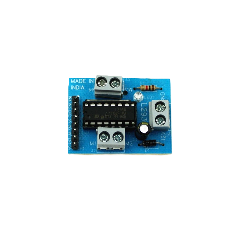
The L293D Motor Driver Module is a versatile and widely-used integrated circuit designed for controlling the direction and speed of DC motors and stepper motors. It is particularly useful in robotics, automotive applications, and various DIY projects where motor control is essential. The L293D is capable of driving up to two DC motors simultaneously or one stepper motor, with current capabilities of up to 600mA per channel. It operates within a supply voltage range of 4.5V to 36V, making it suitable for a variety of low to moderate power applications.
Explore Projects Built with L293D Motor Driver Module


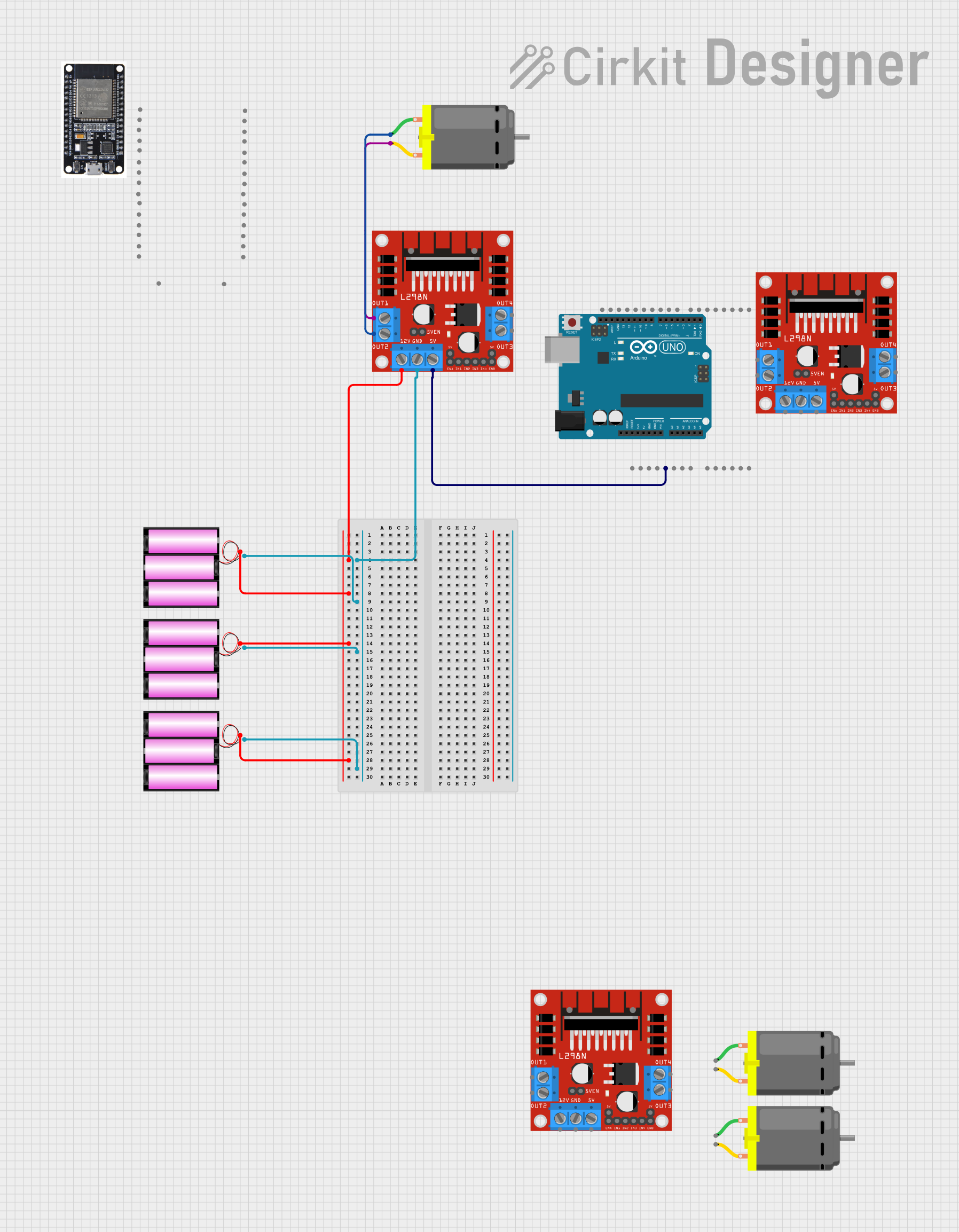
Explore Projects Built with L293D Motor Driver Module
Technical Specifications
Key Technical Details
- Supply Voltage (Vcc1): 4.5V to 36V
- Logic Supply Voltage (Vcc2): 4.5V to 7V (Typically 5V)
- Output Current (per channel): Up to 600mA
- Peak Output Current (per channel): 1.2A (non-repetitive)
- Enable Voltage (for PWM control): 4.5V to 7V
- Input Logic High Level: Min. 2.3V
- Input Logic Low Level: Max. 1.5V
- Operating Temperature: -40°C to +150°C
Pin Configuration and Descriptions
| Pin Number | Name | Description |
|---|---|---|
| 1 | Enable 1,2 | Enables outputs for channels 1 and 2 when high |
| 2 | Input 1 | Logic input for channel 1; sets direction |
| 3 | Output 1 | Output for channel 1; connected to motor |
| 4, 5 | GND | Ground pins (0V reference and heat sink) |
| 6 | Output 2 | Output for channel 2; connected to motor |
| 7 | Input 2 | Logic input for channel 2; sets direction |
| 8 | Vcc2 | Logic supply voltage; powers the IC's internal logic |
| 9 | Enable 3,4 | Enables outputs for channels 3 and 4 when high |
| 10 | Input 3 | Logic input for channel 3; sets direction |
| 11 | Output 3 | Output for channel 3; connected to motor |
| 12, 13 | GND | Ground pins (0V reference and heat sink) |
| 14 | Output 4 | Output for channel 4; connected to motor |
| 15 | Input 4 | Logic input for channel 4; sets direction |
| 16 | Vcc1 | Motor supply voltage; powers the motors |
Usage Instructions
Connecting the L293D to a Circuit
- Connect Vcc1 (Pin 16) to the motor power supply, which should be within the range of 4.5V to 36V.
- Connect Vcc2 (Pin 8) to the logic power supply, typically 5V (e.g., from an Arduino board).
- Connect the ground pins (Pins 4, 5, 12, 13) to the system ground.
- Connect the Enable pins (Pins 1 and 9) to logic high (5V) to enable the outputs, or to a PWM signal for speed control.
- Connect Input pins (Pins 2, 7, 10, 15) to the control signals that determine the motor direction.
- Connect Output pins (Pins 3, 6, 11, 14) to the motor terminals.
Important Considerations and Best Practices
- Always ensure that the power supply voltage does not exceed the maximum rating of the L293D.
- Use decoupling capacitors close to the power pins to minimize voltage spikes.
- For PWM speed control, ensure that the PWM frequency is within the acceptable range for the L293D.
- Avoid running motors at the peak current for extended periods to prevent thermal shutdown or damage.
Example Code for Arduino UNO
// Define motor control pins
#define MOTOR_A_ENABLE 3
#define MOTOR_A_INPUT1 2
#define MOTOR_A_INPUT2 4

void setup() {
  // Set motor control pins as outputs
  pinMode(MOTOR_A_ENABLE, OUTPUT);
  pinMode(MOTOR_A_INPUT1, OUTPUT);
  pinMode(MOTOR_A_INPUT2, OUTPUT);
}

void loop() {
  // Rotate motor A forward
  digitalWrite(MOTOR_A_INPUT1, HIGH);
  digitalWrite(MOTOR_A_INPUT2, LOW);
  analogWrite(MOTOR_A_ENABLE, 255); // Full speed

  delay(2000); // Run for 2 seconds

  // Stop motor A
  digitalWrite(MOTOR_A_ENABLE, LOW);

  delay(1000); // Stop for 1 second

  // Rotate motor A backward
  digitalWrite(MOTOR_A_INPUT1, LOW);
  digitalWrite(MOTOR_A_INPUT2, HIGH);
  analogWrite(MOTOR_A_ENABLE, 255); // Full speed

  delay(2000); // Run for 2 seconds

  // Stop motor A
  digitalWrite(MOTOR_A_ENABLE, LOW);

  delay(1000); // Stop for 1 second
}
Troubleshooting and FAQs
Common Issues
- Motor not running: Check power supply connections, ensure that the Enable pin is high, and verify that the input signals are correct.
- Motor running weakly: Ensure that the power supply can deliver sufficient current, and check for any voltage drops.
- Overheating: This can occur if the motor draws too much current. Make sure the current does not exceed 600mA per channel or use a heat sink.
Solutions and Tips
- Double-check wiring and connections for any loose or incorrect connections.
- Use a multimeter to verify the voltage levels at the power pins and the output pins.
- Implement proper cooling if the module is running hot, such as adding a heat sink or improving air circulation.
FAQs
Q: Can I control a stepper motor with the L293D? A: Yes, the L293D can control a bipolar stepper motor by using two of its channels.
Q: What is the maximum frequency for PWM speed control? A: The L293D can typically handle PWM frequencies up to a few kilohertz. Consult the datasheet for precise limits.
Q: Can I use the L293D to drive a servo motor? A: No, servo motors require a specific PWM signal for position control, which is different from the continuous drive provided by the L293D.