Cirkit Designer Logo
Cirkit Designer
Your all-in-one circuit design IDE
Home / 
Component Documentation

How to Use IR Receiver: Examples, Pinouts, and Specs

Image of IR Receiver
Cirkit Designer LogoDesign with IR Receiver in Cirkit Designer

Introduction

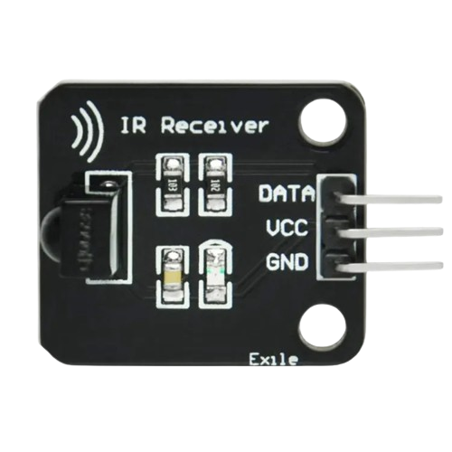
An IR (Infrared) Receiver is an electronic component that is designed to receive and decode infrared signals commonly emitted by remote controls and other IR transmitting devices. These receivers are widely used in consumer electronics, such as televisions, air conditioners, and other household appliances, for wireless control. They are also employed in various DIY projects and robotics for short-range wireless communication.

Explore Projects Built with IR Receiver

Use Cirkit Designer to design, explore, and prototype these projects online. Some projects support real-time simulation. Click "Open Project" to start designing instantly!
Arduino UNO IR Remote Control Receiver
Image of IR pilot: A project utilizing IR Receiver in a practical application
This circuit uses an Arduino UNO to receive and decode infrared signals from a VS1838B IR Receiver. The Arduino is programmed to read the IR signals on digital pin D2 and print the decoded IR codes to the serial monitor.
Cirkit Designer LogoOpen Project in Cirkit Designer
Arduino UNO IR Remote-Controlled LCD Display
Image of IR pilot - LCD1602: A project utilizing IR Receiver in a practical application
This circuit uses an Arduino UNO to receive infrared signals from an IR remote control via a VS1838B IR receiver and displays the received IR codes on a 16x2 I2C LCD screen. The Arduino processes the IR signals and updates the LCD with the corresponding IR code in real-time.
Cirkit Designer LogoOpen Project in Cirkit Designer
ESP32-Based RF Communication System with 433 MHz Modules
Image of 433 mhz: A project utilizing IR Receiver in a practical application
This circuit comprises an ESP32 microcontroller connected to a 433 MHz RF transmitter and receiver pair. The ESP32 is programmed to receive and decode RF signals through the receiver module, as well as send RF signals via the transmitter module. Additionally, the ESP32 can communicate with a Bluetooth device to exchange commands and data, and it uses an LED for status indication.
Cirkit Designer LogoOpen Project in Cirkit Designer
Arduino-Based Doppler Radar with RF Transmission and LCD Display
Image of Doppler Radar: A project utilizing IR Receiver in a practical application
This circuit features an Arduino UNO microcontroller interfaced with an RF 433 MHz Transmitter, a Transmitter RF Module, an LCD screen with I2C communication, and a doppler radar sensor. The Arduino controls the RF transmission and processes the doppler radar's signal, likely for motion detection purposes. The LCD screen is used to display information or statuses, and the RF modules enable wireless communication, possibly to transmit the processed radar data.
Cirkit Designer LogoOpen Project in Cirkit Designer

Explore Projects Built with IR Receiver

Use Cirkit Designer to design, explore, and prototype these projects online. Some projects support real-time simulation. Click "Open Project" to start designing instantly!
Image of IR pilot: A project utilizing IR Receiver in a practical application
Arduino UNO IR Remote Control Receiver
This circuit uses an Arduino UNO to receive and decode infrared signals from a VS1838B IR Receiver. The Arduino is programmed to read the IR signals on digital pin D2 and print the decoded IR codes to the serial monitor.
Cirkit Designer LogoOpen Project in Cirkit Designer
Image of IR pilot - LCD1602: A project utilizing IR Receiver in a practical application
Arduino UNO IR Remote-Controlled LCD Display
This circuit uses an Arduino UNO to receive infrared signals from an IR remote control via a VS1838B IR receiver and displays the received IR codes on a 16x2 I2C LCD screen. The Arduino processes the IR signals and updates the LCD with the corresponding IR code in real-time.
Cirkit Designer LogoOpen Project in Cirkit Designer
Image of 433 mhz: A project utilizing IR Receiver in a practical application
ESP32-Based RF Communication System with 433 MHz Modules
This circuit comprises an ESP32 microcontroller connected to a 433 MHz RF transmitter and receiver pair. The ESP32 is programmed to receive and decode RF signals through the receiver module, as well as send RF signals via the transmitter module. Additionally, the ESP32 can communicate with a Bluetooth device to exchange commands and data, and it uses an LED for status indication.
Cirkit Designer LogoOpen Project in Cirkit Designer
Image of Doppler Radar: A project utilizing IR Receiver in a practical application
Arduino-Based Doppler Radar with RF Transmission and LCD Display
This circuit features an Arduino UNO microcontroller interfaced with an RF 433 MHz Transmitter, a Transmitter RF Module, an LCD screen with I2C communication, and a doppler radar sensor. The Arduino controls the RF transmission and processes the doppler radar's signal, likely for motion detection purposes. The LCD screen is used to display information or statuses, and the RF modules enable wireless communication, possibly to transmit the processed radar data.
Cirkit Designer LogoOpen Project in Cirkit Designer

Technical Specifications

Key Technical Details

  • Supply Voltage (Vcc): Typically 3.3V to 5V
  • Operating Current: 1.5mA to 3mA (depending on model)
  • Carrier Frequency: Commonly 38kHz (varies by model)
  • Reception Distance: Up to 18 meters (depending on model and conditions)
  • Reception Angle: Typically ±45 degrees
  • Output Signal: Digital TTL level signal

Pin Configuration and Descriptions

Pin Number Name Description
1 GND Ground pin, connected to the system ground
2 Vout Output signal pin, goes low when IR signal is detected
3 Vcc Supply voltage pin, typically connected to 3.3V or 5V

Usage Instructions

Connecting the IR Receiver to a Circuit

  1. Power Supply: Connect the Vcc pin to a 3.3V or 5V power supply, depending on your IR receiver's specifications.
  2. Ground: Connect the GND pin to the ground of your power supply.
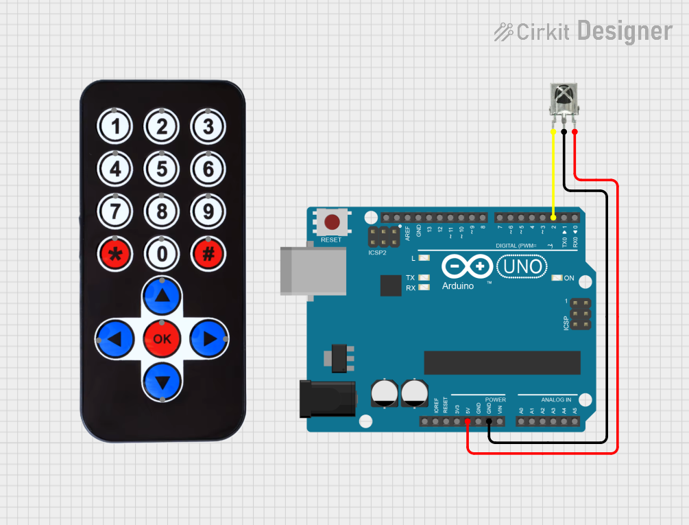
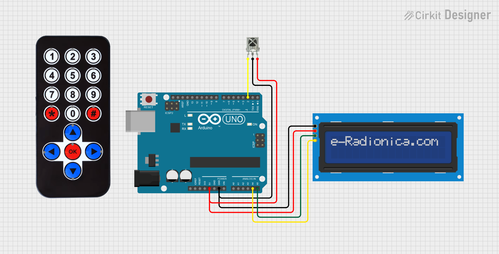
  3. Signal Output: Connect the Vout pin to a digital input pin on your microcontroller, such as an Arduino UNO.

Important Considerations and Best Practices

  • Avoid Exposure to Sunlight: Direct sunlight or other strong IR sources can interfere with the IR receiver.
  • Placement: Ensure the receiver is placed within the specified reception angle for optimal performance.
  • Carrier Frequency: Use an IR transmitter with the same carrier frequency as the receiver (e.g., 38kHz).
  • Bypass Capacitor: Place a 4.7μF to 100μF capacitor between Vcc and GND near the receiver to filter power supply noise.

Example Code for Arduino UNO

#include <IRremote.h>

const int IR_RECEIVER_PIN = 11; // Connect the Vout pin of the IR receiver to pin 11

IRrecv irrecv(IR_RECEIVER_PIN);
decode_results results;

void setup() {
  Serial.begin(9600);
  irrecv.enableIRIn(); // Start the receiver
}

void loop() {
  if (irrecv.decode(&results)) {
    Serial.println(results.value, HEX); // Print the received IR code as a hex value
    irrecv.resume(); // Prepare for the next value
  }
}

Troubleshooting and FAQs

Common Issues

  • No Signal Detected: Ensure the IR receiver is properly powered and connected to the correct pins. Check for obstructions between the transmitter and receiver.
  • Intermittent Operation: This could be due to power supply noise. Add a bypass capacitor as mentioned in the best practices.
  • False Triggers: Strong IR sources like sunlight or halogen lamps can cause false triggers. Shield the receiver from these sources.

Solutions and Tips for Troubleshooting

  • Check Connections: Verify all connections are secure and correct.
  • Test with Known Good Remote: Use a remote control that is known to work to rule out issues with the transmitter.
  • Use Serial Output: Utilize the serial output in the example code to debug and check if the IR receiver is receiving any data.

FAQs

Q: Can I use a 3.3V IR receiver with a 5V system? A: Yes, but ensure that the IR receiver is rated for 5V operation to avoid damage.

Q: How can I increase the range of the IR receiver? A: Avoid placing the receiver near noise sources, use a higher quality receiver, or increase the transmitter's power.

Q: What should I do if the receiver is picking up noise? A: Shield the receiver from potential noise sources and ensure proper grounding. Use a bypass capacitor to filter the power supply.

Q: Can I connect multiple IR receivers to a single microcontroller? A: Yes, you can connect multiple receivers to different digital input pins and modify the code to handle multiple inputs.