How to Use JQ6500: Examples, Pinouts, and Specs
Introduction
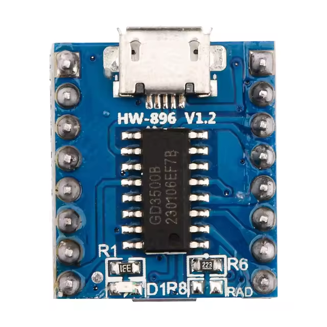
The JQ6500 is a high-quality audio playback module designed for embedded audio applications. It supports popular audio formats such as WAV and MP3, making it versatile for a wide range of projects. The module features a built-in amplifier, a microSD card slot for audio file storage, and can be controlled via serial communication. Its compact size and ease of use make it an excellent choice for projects requiring audio playback, such as voice prompts, alarms, or interactive systems.
Explore Projects Built with JQ6500

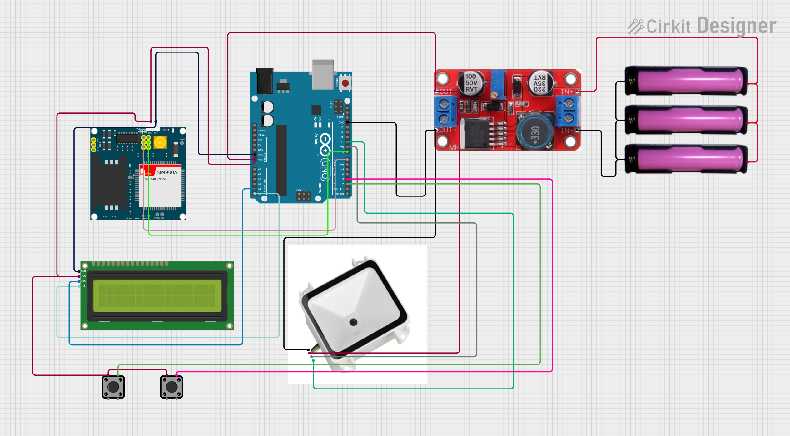

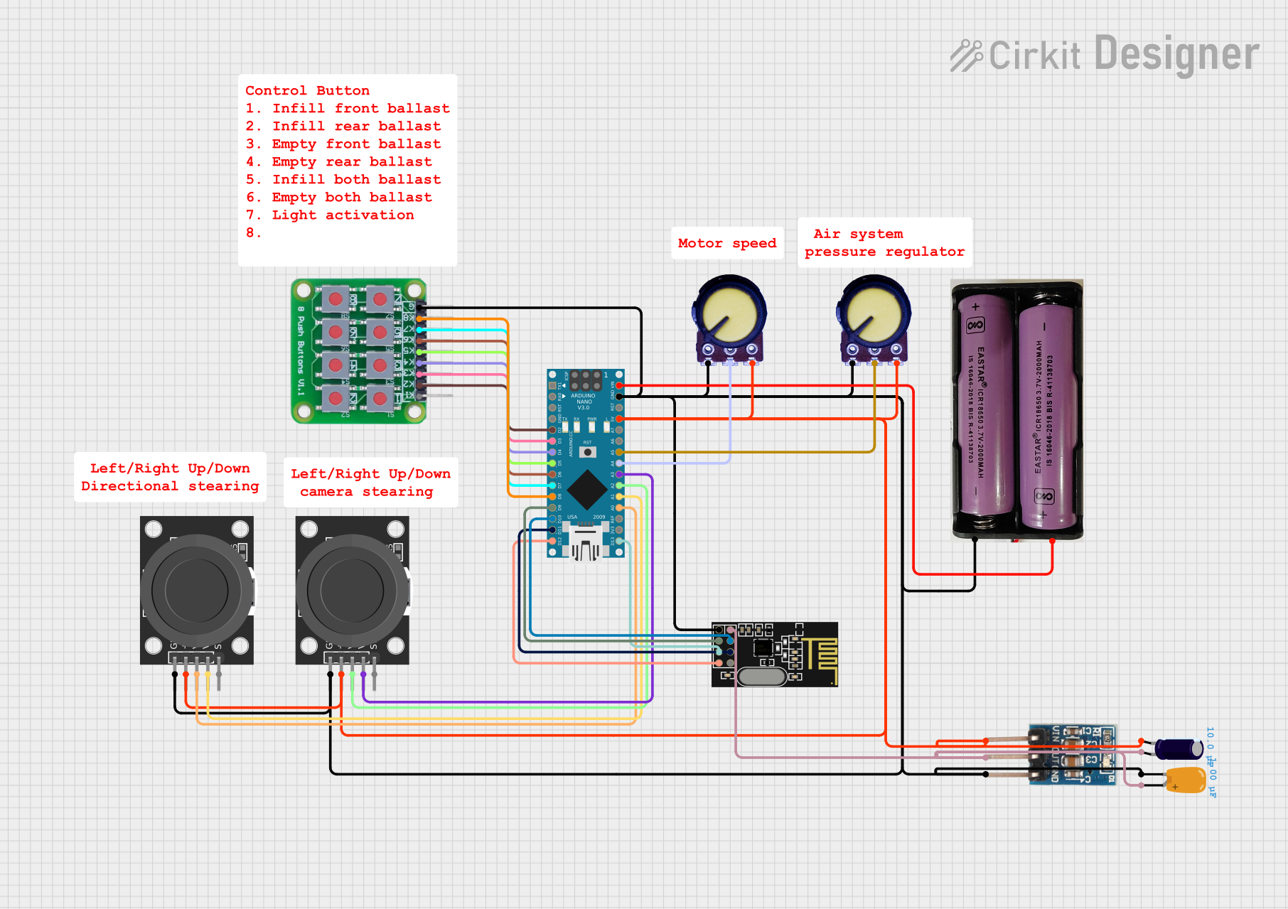
Explore Projects Built with JQ6500
Common Applications and Use Cases
- Voice prompts in consumer electronics
- Audio playback in interactive kiosks
- Alarm systems with custom sound effects
- Educational projects and DIY audio systems
- Embedded systems requiring MP3/WAV playback
Technical Specifications
Below are the key technical details of the JQ6500 module:
| Parameter | Specification |
|---|---|
| Operating Voltage | 3.3V to 5.0V |
| Current Consumption | 20mA (idle), up to 200mA (playback) |
| Audio Formats Supported | MP3, WAV |
| Storage | MicroSD card (up to 32GB) |
| Communication Interface | UART (9600 baud rate by default) |
| Built-in Amplifier | 3W (mono output) |
| Audio Output | Mono speaker or stereo headphone |
| Dimensions | 20mm x 20mm |
Pin Configuration and Descriptions
The JQ6500 module has 8 pins. Below is the pinout and description:
| Pin | Name | Description |
|---|---|---|
| 1 | VCC | Power supply input (3.3V to 5.0V). |
| 2 | GND | Ground connection. |
| 3 | TXD | UART Transmit pin (used for serial communication). |
| 4 | RXD | UART Receive pin (used for serial communication). |
| 5 | SPK+ | Positive terminal for speaker output (mono). |
| 6 | SPK- | Negative terminal for speaker output (mono). |
| 7 | IO1 | General-purpose input/output pin 1 (can trigger specific audio files). |
| 8 | IO2 | General-purpose input/output pin 2 (can trigger specific audio files). |
Usage Instructions
How to Use the JQ6500 in a Circuit
- Power the Module: Connect the
VCCpin to a 3.3V or 5.0V power source and theGNDpin to ground. - Audio Output:
- For a speaker, connect the
SPK+andSPK-pins to a mono speaker. - For headphones, use the stereo headphone jack (if available on your module variant).
- For a speaker, connect the
- Storage: Insert a microSD card containing audio files in MP3 or WAV format. Ensure the files are named appropriately (e.g.,
0001.mp3,0002.mp3) for easy triggering. - Control:
- Use the
RXDandTXDpins for UART communication to control playback via a microcontroller (e.g., Arduino). - Alternatively, use the
IO1andIO2pins to trigger specific audio files directly.
- Use the
Important Considerations and Best Practices
- File Format: Ensure audio files are in MP3 or WAV format and stored in the root directory of the microSD card.
- Power Supply: Use a stable power source to avoid noise or distortion in audio playback.
- Speaker Impedance: Use a speaker with an impedance of 4Ω or 8Ω for optimal performance.
- Serial Communication: The default UART baud rate is 9600. Configure your microcontroller accordingly.
- Triggering via IO Pins: The
IO1andIO2pins can be connected to buttons or other digital signals to play specific audio files.
Example: Using JQ6500 with Arduino UNO
Below is an example of how to control the JQ6500 module using an Arduino UNO via UART:
#include <SoftwareSerial.h>

// Define RX and TX pins for SoftwareSerial
SoftwareSerial mySerial(10, 11); // RX = Pin 10, TX = Pin 11

void setup() {
  mySerial.begin(9600); // Initialize SoftwareSerial at 9600 baud
  Serial.begin(9600);   // Initialize Serial Monitor for debugging

  // Send initialization message
  Serial.println("JQ6500 Audio Module Test");
}

void loop() {
  // Example: Play the first audio file (0001.mp3)
  Serial.println("Playing audio file 0001.mp3");
  mySerial.write(0x7E); // Start byte
  mySerial.write(0x03); // Command length
  mySerial.write(0xA0); // Play command
  mySerial.write(0x00); // File number high byte
  mySerial.write(0x01); // File number low byte
  mySerial.write(0x7E); // End byte

  delay(5000); // Wait for 5 seconds before playing again
}
Notes on the Code
- The
mySerial.write()commands send the necessary bytes to the JQ6500 module to play a specific audio file. - Replace
0x00and0x01with the appropriate file number to play other files.
Troubleshooting and FAQs
Common Issues and Solutions
No Audio Output:
- Ensure the microSD card is properly inserted and formatted as FAT32.
- Verify that the audio files are in MP3 or WAV format and named correctly (e.g.,
0001.mp3). - Check the speaker connections and ensure the speaker impedance matches the module's requirements.
Distorted Audio:
- Use a stable power supply to avoid voltage fluctuations.
- Ensure the speaker impedance is 4Ω or 8Ω.
- Reduce the playback volume if the speaker cannot handle high output power.
Module Not Responding to UART Commands:
- Verify the UART connections (TXD and RXD) between the JQ6500 and the microcontroller.
- Ensure the baud rate is set to 9600 in your code.
- Check for loose or incorrect wiring.
Trigger Pins Not Working:
- Ensure the
IO1andIO2pins are connected to a proper digital signal or button. - Verify that the corresponding audio files are present on the microSD card.
- Ensure the
FAQs
Q: Can the JQ6500 play audio files in a specific folder?
A: No, the JQ6500 requires audio files to be stored in the root directory of the microSD card.
Q: What is the maximum size of the microSD card supported?
A: The JQ6500 supports microSD cards up to 32GB formatted as FAT32.
Q: Can I use the JQ6500 without a microcontroller?
A: Yes, you can use the IO1 and IO2 pins to trigger specific audio files without a microcontroller.
Q: Does the JQ6500 support stereo output?
A: The JQ6500 primarily supports mono output via the SPK+ and SPK- pins. However, some variants may include a stereo headphone jack.