How to Use SparkFun_Beefcake_Relay_Control_Kit: Examples, Pinouts, and Specs
Introduction
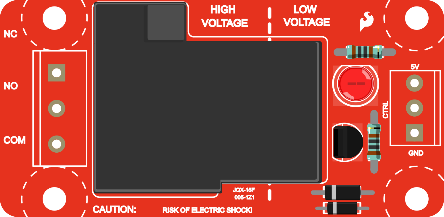
The SparkFun Beefcake Relay Control Kit is designed to facilitate the control of high-power devices and appliances using a low-power signal from a microcontroller such as an Arduino. This kit is ideal for projects that require the switching of devices that operate at higher currents or voltages than a microcontroller can handle directly. Common applications include home automation, industrial controls, and automotive electronics.
Explore Projects Built with SparkFun_Beefcake_Relay_Control_Kit
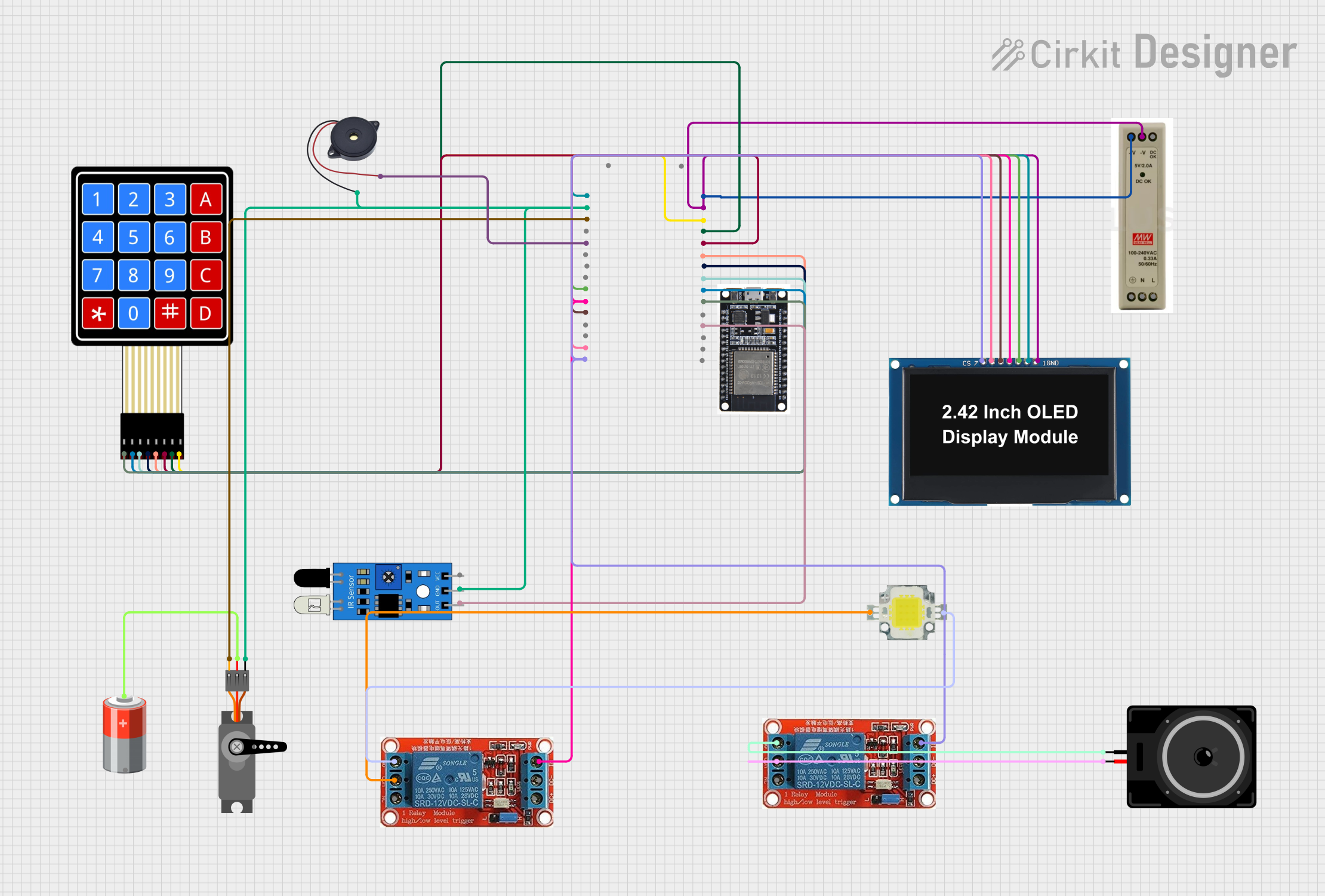
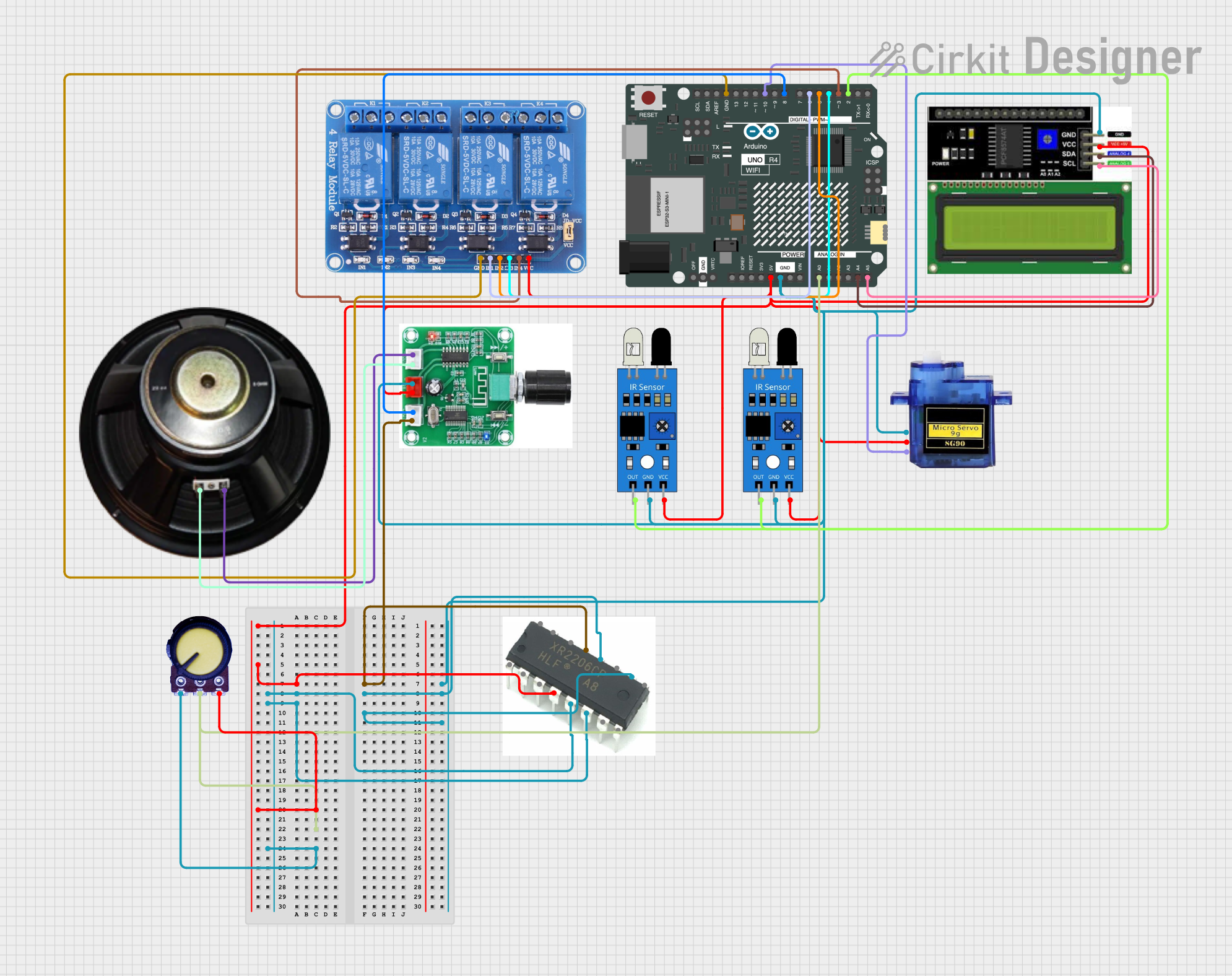

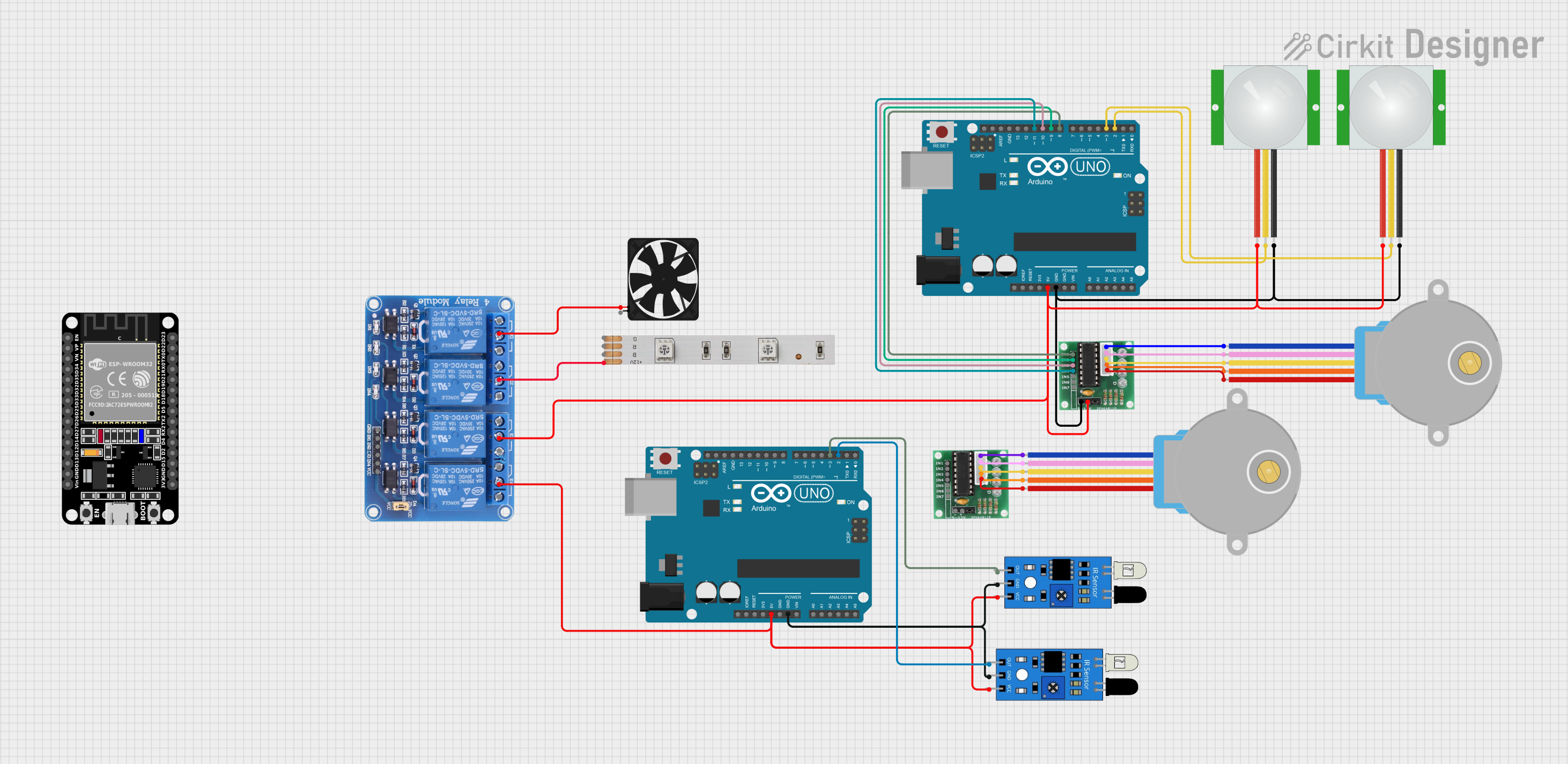
Explore Projects Built with SparkFun_Beefcake_Relay_Control_Kit
Technical Specifications
Key Technical Details
- Control Voltage (from microcontroller): 3.3V to 5V
- Relay Type: Single - SPDT (Single Pole Double Throw)
- Contact Rating: 20A @ 220VAC, 20A @ 30VDC
- Operating Voltage: 5V (from separate power supply)
- Max Switching Voltage: 250VAC, 30VDC
- Max Switching Current: 20A
- LED Indicator: Shows when the relay is activated
Pin Configuration and Descriptions
| Pin Number | Description | Notes |
|---|---|---|
| 1 | Control Input (IN) | Connect to microcontroller output |
| 2 | Ground (GND) | Connect to microcontroller ground |
| 3 | Voltage Input (VCC) | 5V from a separate power supply |
| 4 | Normally Closed (NC) | Relay output pin |
| 5 | Common (COM) | Relay output pin |
| 6 | Normally Open (NO) | Relay output pin |
Usage Instructions
How to Use the Component in a Circuit
Power Connections:
- Connect the VCC pin to a 5V power supply.
- Connect the GND pin to the ground of both the power supply and the microcontroller.
Control Signal:
- Connect the IN pin to a digital output pin on the microcontroller.
Load Connections:
- Connect the high-power load to the Common (COM) and Normally Open (NO) pins for a load that is powered when the relay is activated.
- Use the Normally Closed (NC) pin instead of the NO pin if you want the load to be powered when the relay is not activated.
Important Considerations and Best Practices
- Ensure that the power supply used for VCC is capable of providing sufficient current for the relay coil.
- Do not exceed the maximum voltage and current ratings of the relay contacts.
- Use flyback diodes when controlling inductive loads to prevent voltage spikes.
- Consider using a snubber circuit for highly inductive or capacitive loads to reduce electrical noise.
- Always ensure proper isolation between the low-power control side and the high-power load side.
Example Code for Arduino UNO
// Define the relay control pin
const int relayPin = 2;

void setup() {
  // Set the relay control pin as an output
  pinMode(relayPin, OUTPUT);
}

void loop() {
  // Turn on the relay (activate the connected load)
  digitalWrite(relayPin, HIGH);
  delay(1000); // Wait for 1 second

  // Turn off the relay (deactivate the connected load)
  digitalWrite(relayPin, LOW);
  delay(1000); // Wait for 1 second
}
Troubleshooting and FAQs
Common Issues
- Relay does not activate: Check the control signal voltage and power supply connections.
- Intermittent operation: Ensure that all connections are secure and that the power supply is stable.
- Load does not turn on/off: Verify the load is properly connected to the COM and NO/NC pins and that it does not exceed the relay's ratings.
Solutions and Tips for Troubleshooting
- Double-check wiring against the pin configuration table.
- Use a multimeter to verify the presence of the control voltage and the continuity of the relay contacts.
- If controlling multiple relays, ensure that the microcontroller can source/sink enough current for all relay coils.
FAQs
Q: Can I control this relay with a 3.3V microcontroller? A: Yes, the control input can accept a 3.3V signal.
Q: What is the purpose of the LED indicator? A: The LED indicator provides a visual confirmation that the relay is activated.
Q: Can I switch AC loads with this relay? A: Yes, the relay can switch AC loads up to 20A @ 220VAC, but always ensure proper safety precautions when working with high voltage.
Q: How can I control multiple relays? A: You can control multiple relays by using multiple digital output pins from your microcontroller, one for each relay control input. Make sure your microcontroller can handle the current draw from all relay coils when activated simultaneously.