How to Use 24LC01: Examples, Pinouts, and Specs

Introduction
The 24LC01 is a 1K-bit Electrically Erasable Programmable Read-Only Memory (EEPROM) integrated circuit, capable of storing data that must be preserved during power cycles. This component is commonly used in small-scale data storage applications where a limited amount of non-volatile memory is required. Typical use cases include storing device configurations, calibration data, or small user preferences.
Explore Projects Built with 24LC01
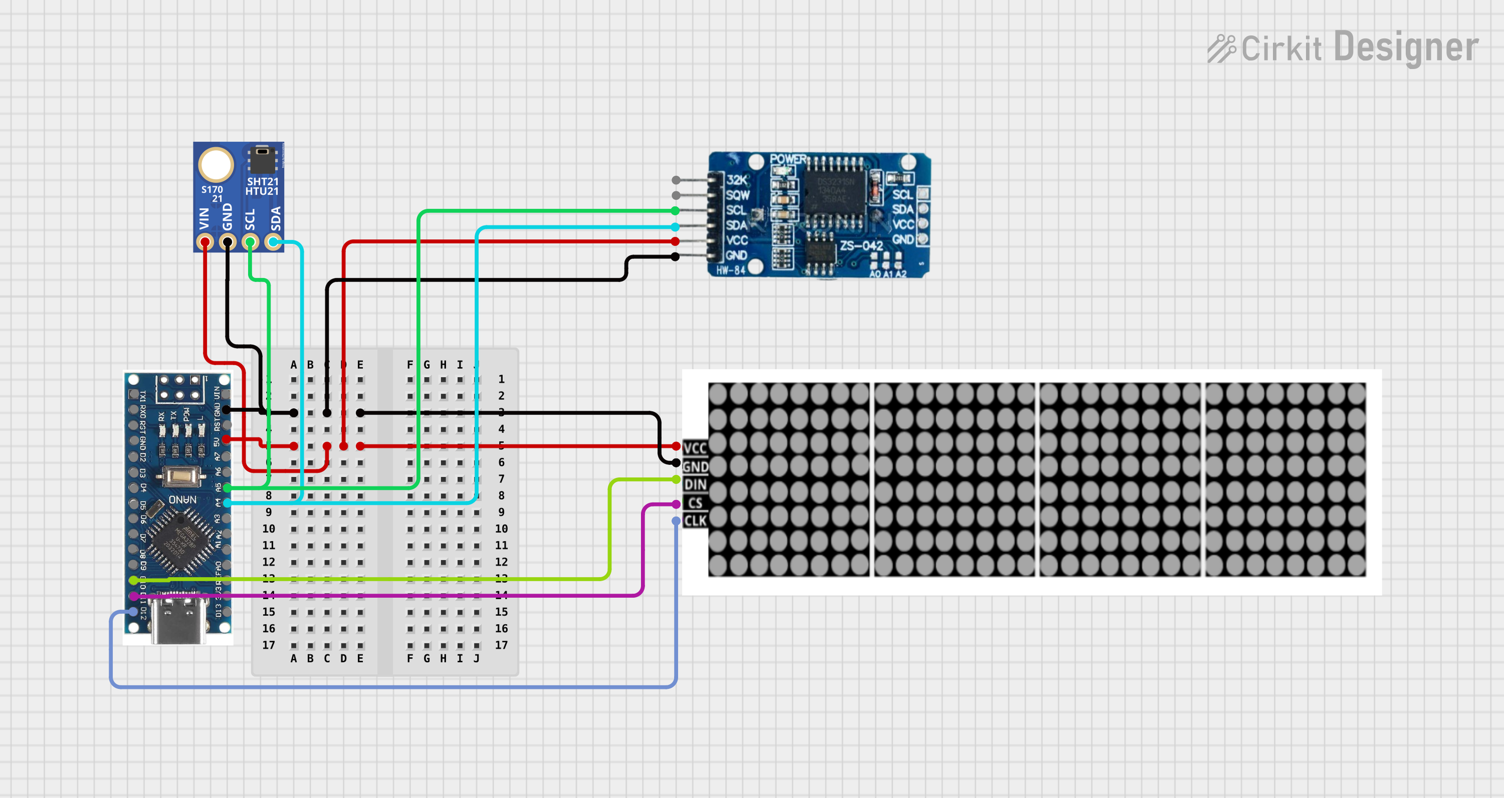

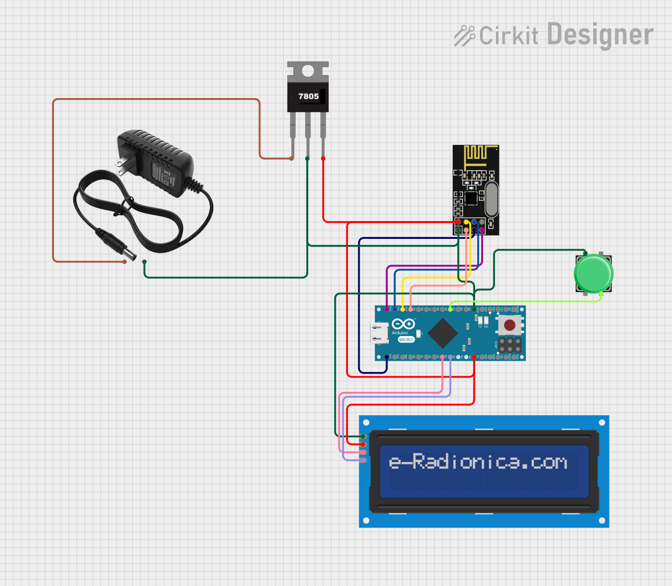
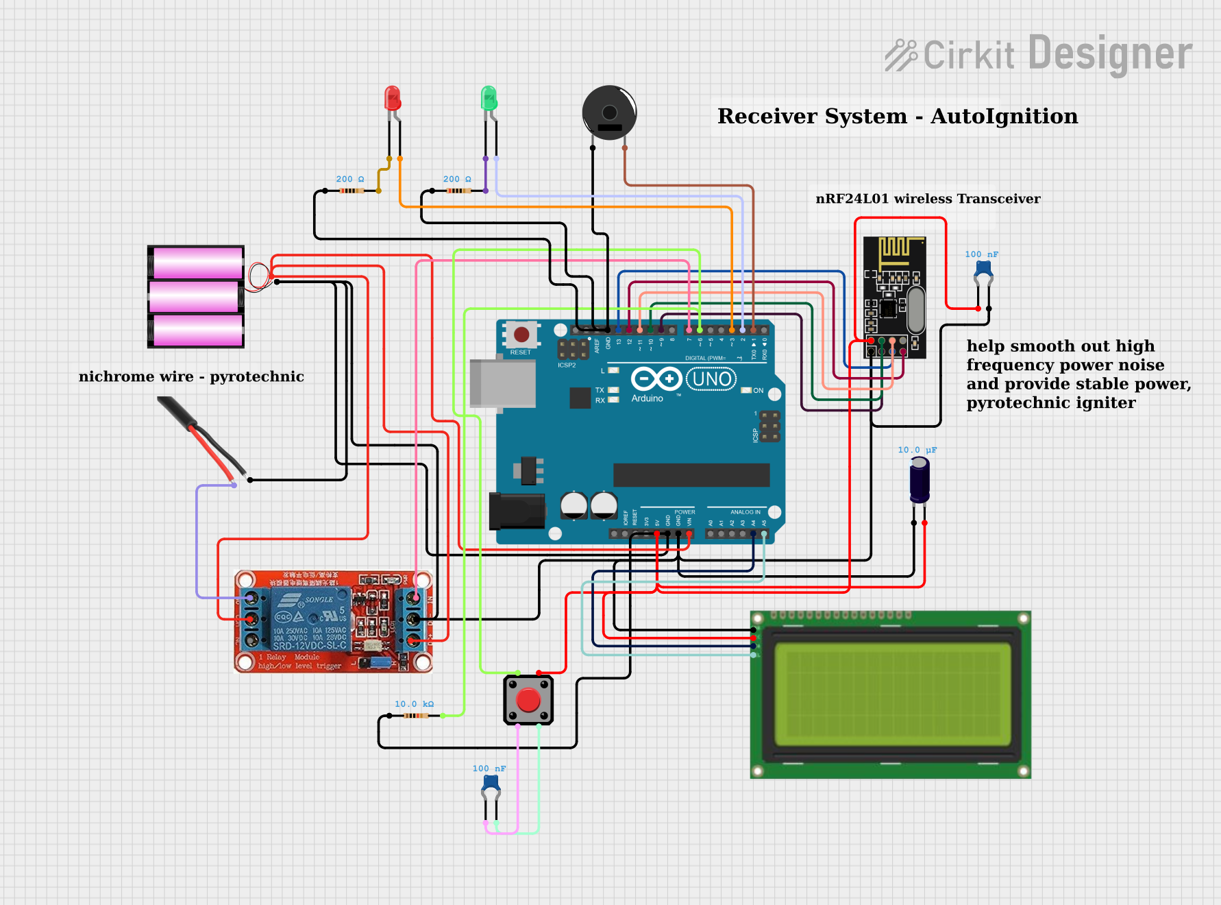
Explore Projects Built with 24LC01
Technical Specifications
Key Technical Details
- Memory Size: 1 Kbit (128 x 8 bits)
- Interface: I²C (Inter-Integrated Circuit)
- Operating Voltage Range: 2.5V to 5.5V
- Write Cycle Time: 5 ms (max)
- Endurance: 1 million write cycles
- Data Retention: >200 years
- Operating Temperature Range: -40°C to +85°C
Pin Configuration and Descriptions
| Pin Number | Pin Name | Description |
|---|---|---|
| 1 | A0 | Address input 0 (LSB) |
| 2 | A1 | Address input 1 |
| 3 | A2 | Address input 2 (MSB) |
| 4 | Vss | Ground (0V) |
| 5 | SDA | Serial Data Line |
| 6 | SCL | Serial Clock Line |
| 7 | WP | Write Protect (active high) |
| 8 | Vcc | Supply Voltage (2.5V to 5.5V) |
Usage Instructions
Interfacing with a Circuit
To use the 24LC01 EEPROM in a circuit:
- Connect Vcc to a 2.5V to 5.5V power supply.
- Connect Vss to the ground of the power supply.
- Connect SDA and SCL to the I²C data and clock lines, respectively.
- Set the A0, A1, and A2 pins to either Vcc or Vss to determine the device's I²C address.
- Optionally, connect the WP pin to Vcc to prevent accidental writes to the EEPROM.
Best Practices
- Use pull-up resistors on the SDA and SCL lines to ensure proper I²C communication.
- Avoid exposing the device to temperatures outside the specified operating range.
- Ensure that the WP pin is properly set when write protection is desired.
- Follow proper ESD precautions when handling the EEPROM to prevent damage.
Example Code for Arduino UNO
#include <Wire.h>

// Define the I2C address for the EEPROM
const int EEPROM_ADDRESS = 0x50; // A2, A1, A0 are connected to GND

void setup() {
  Wire.begin(); // Initialize I2C
  Serial.begin(9600); // Start serial communication at 9600 baud
}

void loop() {
  // Write a single byte (0xAA) to address 0 of the EEPROM
  writeEEPROM(EEPROM_ADDRESS, 0, 0xAA);
  delay(10); // Short delay to ensure the write process is completed

  // Read the byte back from address 0 of the EEPROM
  byte readValue = readEEPROM(EEPROM_ADDRESS, 0);
  Serial.print("Read value: ");
  Serial.println(readValue, HEX); // Print the read value in hexadecimal format

  delay(1000); // Wait for a second before repeating the process
}

void writeEEPROM(int deviceAddress, unsigned int eeAddress, byte data) {
  Wire.beginTransmission(deviceAddress);
  Wire.write((int)(eeAddress >> 8));   // MSB
  Wire.write((int)(eeAddress & 0xFF)); // LSB
  Wire.write(data);
  Wire.endTransmission();

  delay(5); // Max write cycle time per datasheet
}

byte readEEPROM(int deviceAddress, unsigned int eeAddress) {
  byte rData = 0xFF;

  Wire.beginTransmission(deviceAddress);
  Wire.write((int)(eeAddress >> 8));   // MSB
  Wire.write((int)(eeAddress & 0xFF)); // LSB
  Wire.endTransmission();

  Wire.requestFrom(deviceAddress, 1);

  if (Wire.available()) rData = Wire.read();

  return rData;
}
Troubleshooting and FAQs
Common Issues
- Data not persisting: Ensure that the WP pin is not set to write protect mode during a write operation.
- I²C communication failure: Check the pull-up resistors on the SDA and SCL lines and verify the connections.
- Incorrect data read: Confirm that the EEPROM address is set correctly and that there are no shorts or open circuits.
Solutions and Tips
- If the EEPROM is not responding, check the power supply and ground connections.
- Ensure that the I²C bus is not being held by another device.
- Use an oscilloscope to check the integrity of the I²C signals if communication issues persist.
FAQs
Q: How do I set the I²C address of the 24LC01? A: The I²C address is determined by the voltage applied to the A0, A1, and A2 pins. Connect these pins to either Vcc or Vss to set the address.
Q: Can I write to the EEPROM in a single operation? A: Yes, but the maximum amount of data that can be written in a single write cycle is limited by the page size of the EEPROM.
Q: How do I prevent accidental writes to the EEPROM? A: Connect the WP pin to Vcc to enable write protection. When WP is high, write operations are inhibited.
This documentation provides a comprehensive guide to using the 24LC01 EEPROM IC in your projects. For further information, consult the manufacturer's datasheet.