How to Use lidar: Examples, Pinouts, and Specs
Introduction
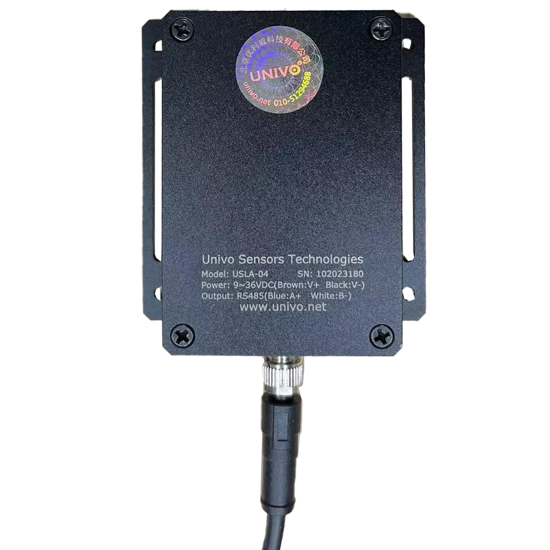
Lidar (Light Detection and Ranging) is a remote sensing technology developed by Univo that uses laser light to measure distances to objects. By emitting laser pulses and analyzing the reflected light, Lidar can create high-resolution maps and 3D models of the surrounding environment. This technology is widely used in various industries due to its precision and versatility.
Explore Projects Built with lidar
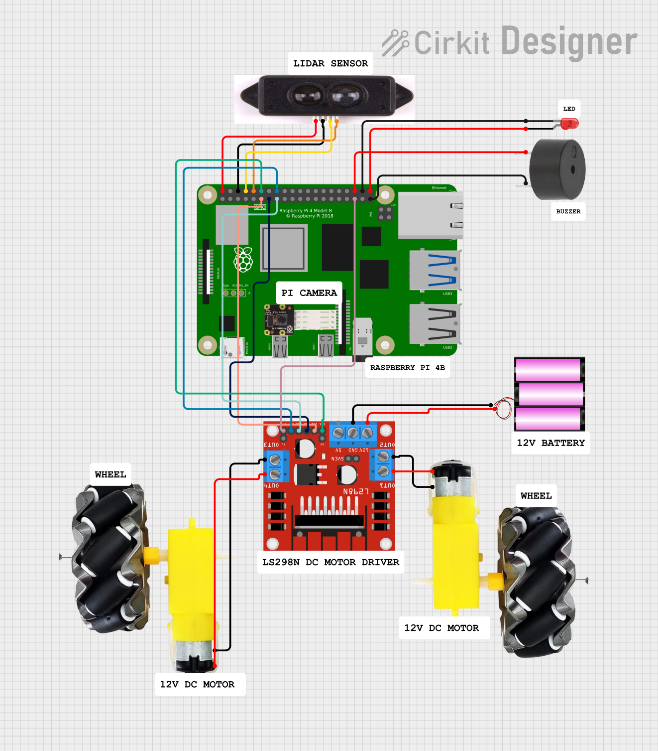
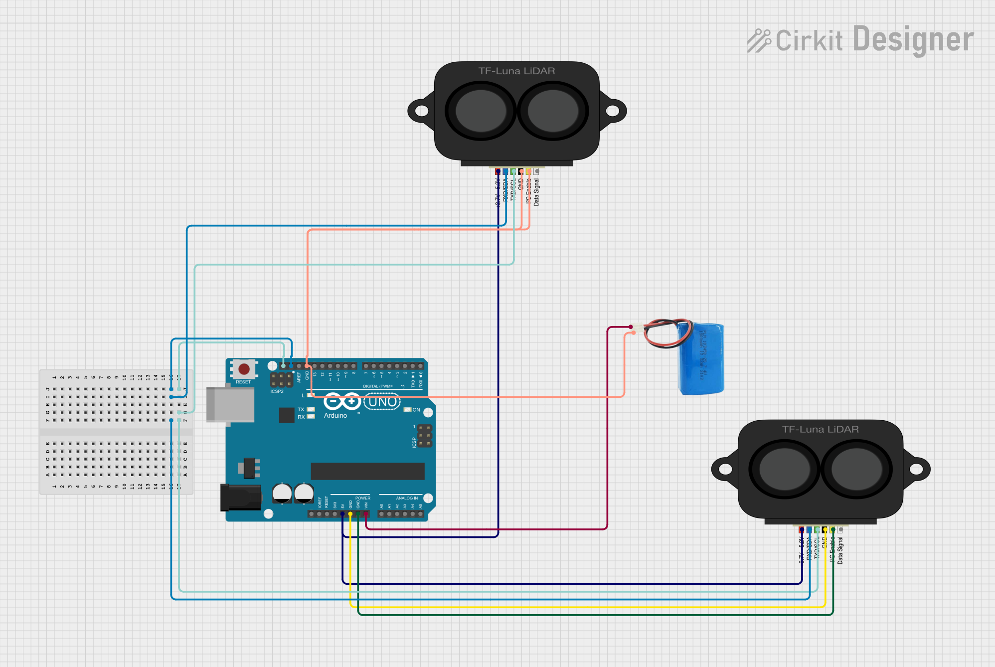
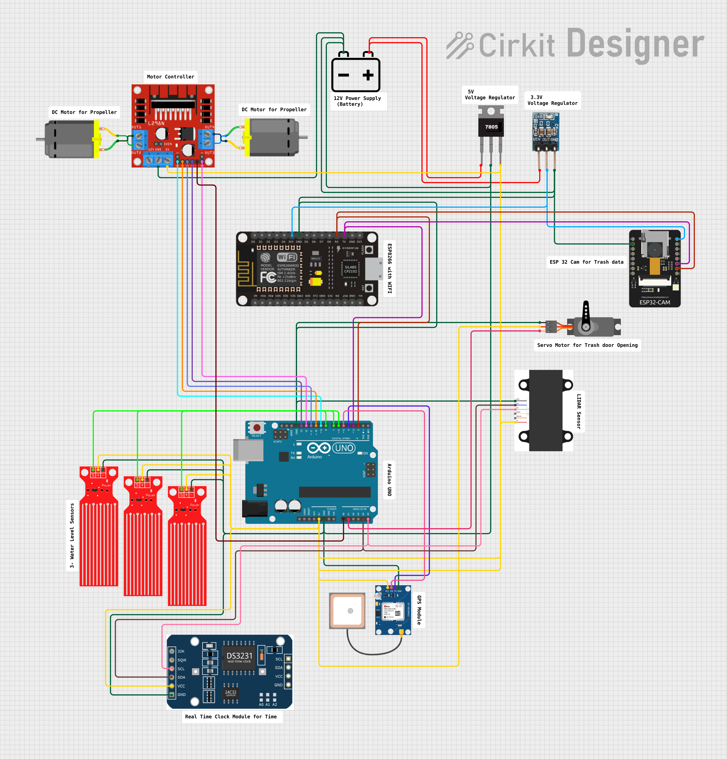

Explore Projects Built with lidar
Common Applications and Use Cases
- Autonomous Vehicles: For obstacle detection, navigation, and mapping.
- Geospatial Mapping: Creating detailed topographic maps and 3D models.
- Robotics: Enabling robots to perceive and interact with their environment.
- Agriculture: Monitoring crop health and land management.
- Construction and Surveying: Measuring distances and creating site models.
- Environmental Monitoring: Tracking changes in forests, coastlines, and other ecosystems.
Technical Specifications
The Univo Lidar module is designed for high performance and reliability. Below are its key technical details:
General Specifications
| Parameter | Value |
|---|---|
| Wavelength | 905 nm |
| Measurement Range | 0.2 m to 40 m |
| Accuracy | ±2 cm |
| Field of View (FoV) | 360° (horizontal), 15° (vertical) |
| Scanning Frequency | 5 Hz to 20 Hz |
| Power Supply Voltage | 5 V DC |
| Power Consumption | 2.5 W |
| Communication Interface | UART, I2C, or CAN |
| Operating Temperature | -10°C to 60°C |
| Dimensions | 60 mm x 60 mm x 50 mm |
| Weight | 150 g |
Pin Configuration and Descriptions
The Univo Lidar module features a standard 6-pin interface for easy integration into various systems.
| Pin Number | Pin Name | Description |
|---|---|---|
| 1 | VCC | Power supply input (5 V DC) |
| 2 | GND | Ground connection |
| 3 | TX | UART Transmit (data output) |
| 4 | RX | UART Receive (data input) |
| 5 | SCL | I2C Clock line |
| 6 | SDA | I2C Data line |
Usage Instructions
How to Use the Component in a Circuit
- Power Supply: Connect the VCC pin to a 5 V DC power source and the GND pin to ground.
- Communication Interface: Choose between UART or I2C for communication:
- For UART, connect the TX and RX pins to the corresponding UART pins on your microcontroller.
- For I2C, connect the SCL and SDA pins to the I2C clock and data lines, respectively.
- Mounting: Secure the Lidar module on a stable platform to minimize vibrations and ensure accurate measurements.
- Data Processing: Use a microcontroller or computer to process the distance and angle data received from the Lidar.
Important Considerations and Best Practices
- Avoid Direct Sunlight: Excessive ambient light can interfere with the laser signal and reduce accuracy.
- Ensure Clear Line of Sight: Remove any obstructions in the Lidar's field of view for optimal performance.
- Use Proper Termination: If using UART, ensure proper termination to avoid signal reflections.
- Heat Management: Operate the module within the specified temperature range to prevent overheating.
Example Code for Arduino UNO
Below is an example of how to interface the Univo Lidar with an Arduino UNO using UART communication:
#include <SoftwareSerial.h>

// Define RX and TX pins for SoftwareSerial
SoftwareSerial lidarSerial(10, 11); // RX = pin 10, TX = pin 11

void setup() {
  Serial.begin(9600); // Initialize Serial Monitor at 9600 baud
  lidarSerial.begin(115200); // Initialize Lidar communication at 115200 baud

  Serial.println("Univo Lidar Initialized");
}

void loop() {
  if (lidarSerial.available()) {
    // Read data from Lidar and print to Serial Monitor
    String lidarData = "";
    while (lidarSerial.available()) {
      char c = lidarSerial.read();
      lidarData += c;
    }
    Serial.println("Lidar Data: " + lidarData);
  }
}
Note: Ensure the Lidar's baud rate matches the value specified in the code (115200 in this case). Adjust the RX and TX pins as needed for your setup.
Troubleshooting and FAQs
Common Issues Users Might Face
No Data Received:
- Cause: Incorrect wiring or communication settings.
- Solution: Double-check the connections and ensure the baud rate matches the Lidar's configuration.
Inaccurate Measurements:
- Cause: Obstructions in the Lidar's field of view or excessive ambient light.
- Solution: Clear the Lidar's path and avoid direct sunlight or reflective surfaces.
Module Overheating:
- Cause: Operating outside the specified temperature range.
- Solution: Ensure proper ventilation and operate within -10°C to 60°C.
Intermittent Data Loss:
- Cause: Loose connections or electrical noise.
- Solution: Secure all connections and use shielded cables if necessary.
FAQs
Q: Can the Univo Lidar detect transparent objects?
A: No, the Lidar may struggle to detect transparent or highly reflective surfaces.Q: What is the maximum range of the Univo Lidar?
A: The maximum range is 40 meters under optimal conditions.Q: Can I use the Lidar outdoors?
A: Yes, but avoid direct sunlight and extreme weather conditions for best results.Q: Is the Lidar compatible with Raspberry Pi?
A: Yes, the Lidar can be interfaced with Raspberry Pi using UART or I2C communication.
By following this documentation, users can effectively integrate and operate the Univo Lidar module in their projects.